LRM Manual CMGP
CMGP Manuals No. 01: LRM Manual Message from the Secretary 2 Local Road Management Manual for Local Government Units Department of the Interior and Local Government Oiffce of Project Development Services 2018
Local Road Management Manual for Local Government Units Department of the Interior and Local Government Oiffce of Project Development Services 2018
Local Road Management Manual 7 The Department of the Interior and Local Government (DILG) is the primary catalyst for excellence in local governance that nurtures self-reliant, progressive, orderly, safe, and globally competitive communities sustained by an empowered citizenry. Learn more at dilg.gov. ph or follow DILG Philippines. Published by: Oiffce of the Project Development Services Conditional Matching Grant to Provinces Department of the Interior and Local Government 24/F DILG-NAPOLCOM Center EDSA corner Quezon Avenue, Quezon City
Message from the Secretary 8 FOREWORD The local road network serves every sector in the community. Along with the changes that are happening in our time is our government’s realization of the irrefutable importance of local roads in bringing positive change and development, even in the most far-lfung areas of the country. These roads serve as conduits linking farmers to markets, students to schools and workers to their places of employment. Apart from being an enabler in the execution of robust everyday social and economic activities, good local roads play a vital role in the delivery and provision of emergency services from our government, as manifested during the most recent events in Marawi City and calamities experienced by our countrymen.
Local Road Management Manual 9 That being said, our current administration is committed in ensuring that local roads are rightfully managed, maintained and continually improved to effectively service the citizens. This commitment is shared by our Local Government Units who are in the frontline of local road management. In 2014, the National Government, through the Department of the Interior and Local Government and in partnership with the Australian Government through the Provincial Road Management Facility (PRMF) Program, started developing a Local Roads Management Manual. The manual, which aims to aid the LGUs in performing their crucial role in managing roads, will serve as a guide for their construction, repair, rehabilitation, improvement and maintenance. Today, through the Conditional Matching Grant to Provinces (CGMP) for Road and Bridge Repair, Rehabilitation and Improvement Program, the manual has been enhanced and is ready for dissemination to the Provincial Governments. Inaasahan natin na makakatulong ng lubos ang LRM Manual na ito sa tuloy-tuloy na pagbuo natin ng matatag, patuloy na umuunlad at masasayang mga komunidad sa buong bansa. Eduardo M. Ano Secretary
Preface 10 PREFACE Local roads are key components of the Philippine Road Network. Local roads support the movement of people and goods among communities, production areas, and markets. The development and management of local roads are mandates of Local Government Units (LGUs) by virtue of the Local Government Code of 1991. Local Road Management is considered a critical function of LGUs as these provide access to public goods and services. In pursuit of its function to assist in improving the capabilities of LGUs, the Department of the Interior and Local Government (DILG) has prepared a Local Road Management (LRM) Manual. This has been possible through the technical assistance and support of the Australian Government through the Provincial Road Management Facility (PRMF) Program which ran from 2009— 2016. PRMF was implemented in ten partner provinces in the Visayas (Aklan, Guimaras, and Bohol), and Mindanao (Agusan del Sur, Bukidnon, Davao del Norte, Lanao del Norte, Misamis Occidental, and Surigao del Norte). Currently, DILG, in partnership with DBM, is implementing a Program that took off from the PRMF Program called Conditional Matching Grant to Provinces for Road Repair, Rehabilitation, and Improvement. CMGP is implemented in all Provinces nationwide, and aims to provide assistance to Provinces for provincial road works and institutionalize governance reforms in Local Road Management (LRM) and Public Financial Management (PFM). The LRM Manual aims to provide guidance on the planning, programming, design, construction, and maintenance of local roads. The manual will be a valuable tool for LGUs in sustainably managing their local road network. With this, LGUs could improve its local road management practices which shall result to a more effective and eiffcient delivery of front-line services. This can only be realized through a well-maintained and responsive local road network that is properly developed and managed by LGUs.
Local Road Management Manual 11 TABLE OF CONTENTS CHAPTER 1: INTRODUCTION AND FRAMEWORK Introduction. . . . . . . 14 Local Road Management . . . . 16 General Structure of the Manual . . . . 17 Overview of the Philippine Road Network. . . 18 CHAPTER 2: LOCAL ROAD ADMINISTRATION Administrative Classiifcation of Roads. . . . 22 Other Functional Classiifcation of Local Roads. . . 27 Administrative Functions of LGUs over Local Roads. . 29 Right-of-Way (ROW) Widths of Local Roads. . 36 Conversion of Local Roads. . . . 37 Local Engineers’ Oiffces . . . . . 37 Role of National Government Agencies in Local Road Management . .. . 42 CHAPTER 3: LOCAL ROAD PLANNING Local Development Planning Framework in the Philippines. 49 Local Road Planning Process. . . . . 53 Planning Approaches for Local Road Networks. . . 58 Inventory of Local Roads. . . . . 64 Annual Programming for Local Roads and Local Budgeting Process. . . . . 93
Table of Contents 12 CHAPTER 4: LOCAL ROADS SURFACE TREATMENT OPTIONS Local Road Management Process. . . . . 101 Surface Treatment Options for Local Roads. . . . 108 Recommended Pavement Options for Local Roads. . . 120 Suggested Reference Standards for Local Roads. . . 121 Local Road Safety, , , , , , . 125 Standard Technical Speciifcations for Local Road Projects, . 129 CHAPTER 5: LOCAL ROAD QUANTITY CALCULATION AND COST ESTIMATION Quantity Calculation and Cost Estimation Process. . . 131 Project Development Cost as a Percentage of Construction Cost. . . . . . . 132 Quantity Calculation. . . . . . . 134 Cost Estimation. . . . . . . 136 CHAPTER 6: LOCAL ROAD CONSTRUCTION MANAGEMENT Project Cycle for Local Road Construction. . . . 148 Construction Supervision. . . . . . 151 Contract Management. . . . . . . 177 Quality Assurance (QA) and Quality Control (QC). . . 187 Construction Safety and Health (CSH). . . . . 192 Constructors Performance Evaluation System (CPES). . . 196 CHAPTER 7: LOCAL ROAD MAINTENANCE MANAGEMENT Road Maintenance. . . . . . . 201 Asset Management. . . . . . . 201 Types of Maintenance Activities. . . . . . 203 Common Road Distress. . . . . . 206 Elements of a Maintenance Project. . . . . 207 Suggested Minimum Frequency of Maintenance Activities for Local Gravel Roads. . . . . 207 Cost Estimates for Local Road Maintenance. . . . 213 Maintenance of Sealed Pavement (Paved Local Roads). . . 215
Local Road Management Manual 13 CHAPTER 8: LOCAL ROAD ENVIRONMENTAL SAFEGUARDS The Philippine Environmental Impact Statement System (PEISS). . . . . 225 Other Relevant Philippine Environmental Laws. . . 227 Local Government Policies. . . . . 228 The Revised PEISS Manual of Procedures. . . 229 Practical Environmental Guidelines for Local Road Management Activities. . . . . . 234 Environmental Management System (EMS) for Road Network Development. . . . . 237 Climate Change Considerations. . . . 240
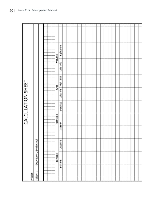
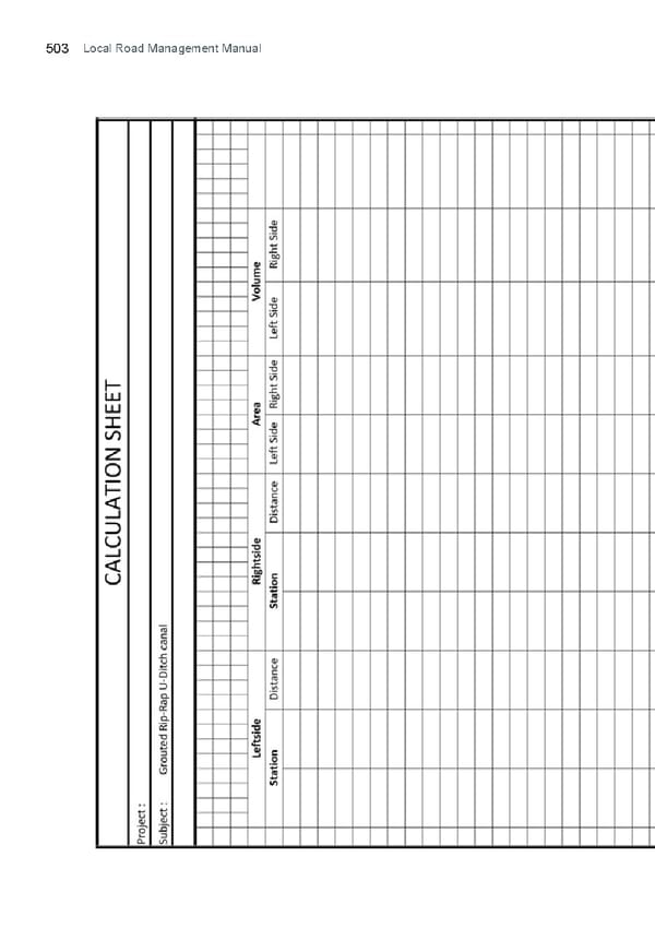
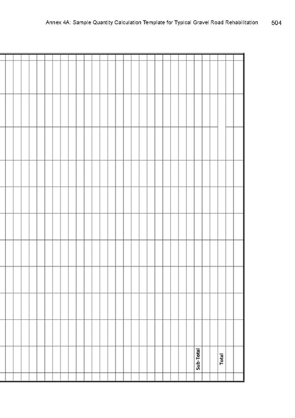
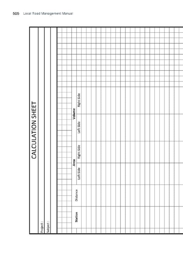
Table of Contents 14 ANNEXES Annex 2A : Suggested Outline for Local Road Network Development Plan Annex 2B : DILG Guidelines on the Development of the Local Roads Network Development Plan (LRNDP) Annex 2C : Template for Local Road Inventory Annex 2D : Template for Local Road Inventory Summary Annex 2E : Template for Local Road Traiffc Count Annex 3A : Reference Guidelines for Local Gravel Road Rehabilitation Annex 3B : Reference Guidelines for Asphalt Pavement Annex 3C : Reference Guidelines for Concrete Pavement Annex 3D : DPWH Department Order No. 11, Series of 2014 Annex 4A : Quantity Calculation Template Annex 4B : Cost Estimation Template Annex 5 : Activity Standards for Local Gravel Road Maintenance Annex 6 : Road and Bridge Infrastructure Vulnerability Assessment Guidelines A copy of the Guidelines on the Implementation of Projects under the Conditional Matching Grant to Provinces for Road and Bridge Repair, Rehabilitation, and Improvement can be accessed online at: https://tinyurl.com/cmgpguidelines2020; www.dilg.gov.ph; and www.cmgpprogram.com/ A copy of the Guidelines on the Implementation of Projects under the Special Local Road Fund (SLRF) of the Motor Vehicle Users Charge Law can be accessed online at: tiny.cc/SLRFGUIDELINES
Local Road Management Manual 15 CHAPTER 1 INTRODUCTION & FRAMEWORK I. Introduction As a function devolved from the National Government to Local Government Units under the Local Government Code of 1991, the management of local road networks is one of the most important functions undertaken by LGUs. To assist the LGUs in the delivery of their local road management functions, the Department of the Interior Local Government (DILG) has prepared a Local Road Management (LRM) Manual that presents tools, standard practices, technical standards, and recommendations for LGUs to sustainably manage their road assets. The manual aims to impart a deeper knowledge and understanding of how an effective and sustainable local road management contributes to the social and economic well-being of a society, and hopes to impart a deeper appreciation of rehabilitation
Introduction 16 and routine and periodic maintenance of existing local roads as this will help the LGUs ensure that the local road network is sustained in fair-to-good condition, which will facilitate more eiffcient service to the public. The Manual sets out the conceptual approaches to better local road management, which shall be deifned, discussed and presented throughout all chapters. Guidance is given on the planning, design, prioritization, programming, implementation and maintenance of local road projects in consideration of the whole local road network. Guidance is particularly given on the reference standards for the rehabilitation and routine and periodic maintenance of local gravel roads. The LRM Manual adopts established practices, standards and approaches on planning, design, construction and maintenance that are relevant and appropriate for local roads, given the institutional capacity of local governments. The LRM Manual seeks to provide the following beneifts to LGUs: • Clarity on responsibilities of LGUs on the administration and management of local roads; • Objective prioritization of local roads; • Linking road planning to work programming and management; • Appropriate engineering interventions to local road conditions; • Reliable estimation of costs for local roads; • Local gravel roads designed and built to standards; • Improve supervision of local road construction; • Longer life span of local roads through proper maintenance; and • Minimize effects of local roads to environment.
Local Road Management Manual 17 II. Local Road Management Local Road Infrastructure, through devolution and decentralization underwritted in the Sections 17 (a) and (b) of the Local Government Code of 1991, are considered as basic facilities that LGUs should provide withing its jurisdiction. As mentioned earlier in this material, local roads are critical infrastructure that provide and accelerate the delivery of public services and goods. The development and management of local road networks is therefore central to this mandate. DILG, as the National Government Agency with oversight functions on Local Government Units, is mandated to provide technical assistance and support to LGUs. Hence, the programs and efforts of the Department to assist LGUs towards the improvement of their institutional capacities in local road management. Local road management is the planning, prioritizing, and sustainably managing the local road network in consideration of the envisioned socioeconomic development of the LGU. In simple terms, local road management is the planning and implementation of investments on local roads based on the function and condition of the local road network as a support to the overall economic development of the LGU. The DILG LRM Manual is a simple technical reference for LGUs on how they can ably plan and manage their local road network.
Introduction 18 III. General Structure of the Manual The Manual aims to assist the local engineering oiffces in the delivery of local road management functions. It is in this context that this Manual is structured as follows: Chapter 1 – Introduction. This chapter introduces the objectives, rationale and structure of the Manual and a brief overview of the road inventory in the Philippines; Chapter 2 – Local Road Administration. This chapter discusses the basic administrative functions of LGUs for local roads within its administrative jurisdictions; Chapter 3 – Local Road Planning. This chapter discussed planning and programming process for local roads within the context of the over-all local road network. This chapter also deals with the programming and budgeting of local roads; Chapter 4 – Local Road Surface Treatment Options. This chapter explains the basic principles of local road management and appropriate surface treatment interventions for local roads given normal conditions. Annexes to this chapter details reference guidelines for local road with gravel, asphalt and concrete pavements; Chapter 5 – Local Road Quantity Calculation and Cost Estimation. This chapter aims to improve the preparation of the program of work being prepared by the local engineering oiffces. This should lead to a more realistic and accurate contract cost for road projects; Chapter 6 – Local Road Construction Management. This chapter discusses the standard practices for construction supervision and contract management roles of local engineering oiffces for typical road projects; Chapter 7 – Local Road Maintenance Management. Road maintenance is an important asset preservation function of the local engineering oiffces. This chapter details road maintenance activities that the local engineering oiffces should undertake to preserve their road assets; and
Local Road Management Manual 19 Chapter 8 – Local Road Environmental Safeguards. This chapter discusses environmental management practices to ensure the environmental and social sustainability of local roads. The safeguards are based on the national framework for environmental management of road projects. III. Overview of the Philippine Road Network The Philippine Road Network is an integral component of the country’s transportation infrastructure. Roads are classiifed as National or Local Roads. Total Length 217,643.57 km
Introduction 20 National Roads
Local Road Management Manual 21 Unpaved Unpaved Unpaved 7,903 11,855 5,400 km For road upgrading For road upgrading For road upgrading fair-to-good Paved fair-to-good Paved fair-to-good Paved paved roads 2,198 paved roads 5,816 paved roads 8,106 km 2,577 1,346 for rehab 2,028 km
Chapter 2: Local Road Administration 22 CHAPTER 2 LOCAL ROAD ADMINISTRATION
Local Road Management Manual 23 1. Administrative Classiifcation of Roads As illustrated in the previous chapter, the Philippine Road Network is classiifed into and managed by different entities. The National Government through the Department of Public Works and Highways has jurisdiction over National Roads, and Local Government Units have jurisdiction over local roads. The administration of roads according to their classiifcation is shown in table 2.1 below: Table 2.1 Administration and Classiifcation of Roads Executive Order No. 113 (EO 113) Series of 1955 formally establishes a system of classiifcation of roads in the Philippines. EO 113 empowers the then Department of Public Works and Communications to recommend to the President the classiifcation of roads and highways into national, provincial, city and municipal roads including prescribing standard widths of right-of-way. The previous Ministry of Public Works and Highways (MPWH) was reorganized into the Department of Public Works and Highways (DPWH) through Executive Order No. 124 (EO 124) Series of 1987. DPWH, by virtue of EO 124, was given the mandate to classify roads and highways into national, regional, provincial, city, municipal,
Chapter 2: Local Road Administration 24 and barangay roads and highways, based on objective criteria it shall adopt; and to provide or authorize the conversion of roads and highways from one category to another. The issuance and adoption of the Design Guidelines, Criteria and Standards (DGCS) for Public Works and Highways by then MPWH (now DPWH) in 1989 provided a standard classiifcation for national, provincial, city, municipal and barangay roads. The oiffcial functional classiifcations of roads as deifned in the actual and speciifc provisions of EO 113 and the MPWH DGCS are detailed in Table 2.2. These administrative jurisdictions are prior to the implementation of devolution and decentralization of frontline functions to the LGUs. During this time, the National Government still had administrative jurisdiction over local roads. The classiifcation of roads deifned in the MPWH DGCS remains the most current government statute specifying the oiffcial functional and administrative classiifcation of roads and highways in the country (except the funding allocation which have been devolved to LGUs by virtue of RA 7160).
Local Road Management Manual 25 Table 2.1 Administration and Classiifcation of Roads Road Oiffcial Function Classiifcation (Actual Provisions) Classiifcation Executive Order No. 113, Series MPWH (now DPWH) of 1955 Design Guidelines, Criteria, and Standards National Section 1) Section 1.321, Part 3, Roads Volume II) National Roads consist of two (2) classes namely, national Public roads, declared primary and national secondary. as national roads by the National primary forms part President of the Philippines of the main trunk-line system upon recommendation of continuous in extent; roads the Minister of Public Works which are now declared national and Highways satisfying roads except those not forming the conditions set forth parts of the continuous system, under Executive Order such as roads leading to national No. 113, establishing the airports, sea ports and parks, classiifcation of roads. etc., or coast-to-coast roads National roads are classiifed not forming continuous parts of as primary and secondary the trunk line system; and city roads. The former forms the roads and street forming the part of the main highway secondary trunk line system not trunkline system which is classiifed as “primary roads”, but continuous in extent; the shall exclude “feeder road”. All latter includes all access national roads, whether primary roads forming a secondary or secondary, shall be declared trunkline system as such by the President of the Philippines upon the recommendation of the Secretary of the Department of the Public Works and Communications. National Roads shall have a right-of-way of not less than twenty (20) meters, provided the Secretary of Public Works and Communications upon the recommendation of the Provincial and City Boards and the Commissioner of Public
Chapter 2: Local Road Administration 26 National Roads Highways that a right-of-way of at least 60 meters shall be reserved for roads constructed through unpatented public and and at least one hundred twenty (120) meters reserved through naturally forested areas of aesthetic or scientiifc value. (Section II) “National Aid” roads are those provincial and city roads of suiffcient importance which may be incorporated eventually into the national system and are so declared as such by Provincial (Section III) (Section 1.322, Part 3, Roads Volume II) All roads connecting one municipality with another Roads connecting one municipality, the terminal to municipality to another, the be the public plazas; all roads terminal to be the public extending from a municipality, plaza; roads extending or from a provincial or national from one municipality road to a public wharf or or from a provincial or railway station and any other national road to a public road which may be so called wharf, or railway station. designated by the Secretary of For purposes of allocating Public Works national aid maintenance
Local Road Management Manual 27 and Communications upon funds, a provincial the request of the Provincial road is designated and Board concerned and upon accepted as such by favorable recommendation o the Minister of Public the Commissioner of Public Works and Highways, Highways, provincial roads upon recommendation shall have a right-of-way of not of the Provincial less than iffteen (15) meters, Board (Sangguniang which may be widened to Panlalawigan). twenty (20) meters, provided that a right-of-way of at least sixty (60) meters shall be reserved for roads constructed through unpatented public land. City Roads (Section IV) (Section 1.323, Part 3, Volume II) All highways not included in the above classiifcations. Municipal Roads/streets within the and city roads shall have a urban area of the city not right-of-way of not less than classiifed as provincial or ten (10) meters; provided that national roads. the principal streets of town sites located on public lands shall have a width of sixty (60) Municipal Roads (Section 1.324, Part 3, meters and all other streets a width of not less than iffteen Volume II) (15) meters. Roads/streets within Municipal Governments the poblacion area Barangay Council of a municipality not classiifed as national or provincial roads. Barangay Roads (Section 1.325, Part 3, Volume II) Roads located outside the poblacion area of a municipality or urban area of a city and those outside industrial, commercial, or residential subdivision
Chapter 2: Local Road Administration 28 Barangay Roads cont. (access roads to subdivision are not barangay roads), and which act as a feeder from farm-to-market roads, and are not otherwise classiifed as national, provincial, city, or municipal roads. Barangay roads must have the following: Road right-of-way: 10.00m minimum Width of traveled way: 4.00 minimum Allowable grade: 10% maximum The authority of LGUs to develop and manage the local road network derives from Republic Act No. 7160 (RA 7160), otherwise known as the Local Government Code of 1991. Sections 17 (b) (1), (2), (3) and (4) of RA 7160 mandates all LGUs to fund, provide and manage frontline basic services and facilities, which include local roads among others. 2. Other functional classiifcation of local roads There is a wide spectrum of development assistance towards local roads ifnanced and implemented by the National Government through its sectoral agencies and Oiffcial Development Assistance (ODAs). Local roads are also often classiifed in accordance to the development objectives by the respective implementing agency. However, such roads are oiffcially still classiifed as local roads and either as provincial, city, municipal or barangay, depending on which LGUs has administrative jurisdiction thereof.
Local Road Management Manual 29 If such subject roads are within the administrative jurisdiction of an LGU, it is recommended that the provisions of this manual be adopted for all works related to local road management (whether new construction, improvement, rehabilitation, maintenance, etc). Typical functional classiifcations of local roads outside of administrative jurisdiction are listed in Table 2.3. There may be speciifc references or guidelines for the design and implementation of such local road projects. It is suggested that such speciifc guidelines may be compared with the provisions of the manual. Any conlficts arising from differences between these documents may be resolved through a mutual agreement between DILG, the LGU concerned and the relevant implementing government agency. IrrigationNational Service and access DPWH Design Service Irrigation roads are roads with Guidelines, and Access Administration irrigation systems, Standards, and Roads (NIA) whether national, Criteria for DPWH- communal or private NIA Projects in nature. National irrigation systems, Philippine Agricultural including services Engineering and access roads, Standards for Farm- are operated and to-Market Roads for maintained by NIA. DA-NIA Projects Irrigators Association operated and maintains communal irrigation systems including service roads. Service roads on embankments of major canals are linked with roads leading to villages or towns. Access roads link the irrigation systems to provincial or national roads. Service and access roads also serve as farm-to-market roads. NIA coordinates with DPWH and DA in road construction and rehabilitation.
Chapter 2: Local Road Administration 30 3. Administrative Functions of LGUs over Local Roads The Local Government Code (RA 7160) empowers all LGUs to discharge functions and responsibilities that have been devolved to them, particularly the provision of basic services and facilities. Amongst the functions vested unto the LGUs is the development and management of local roads. Pursuant to Section 17 of the Local Government Code, LGUs are mandated to provide services in relation to local roads, which are summarized in Table 2.4. This table also details other provisions set by RA 7160 on the functions of LGUs toward local road management. The Local Government Code has provisions when a certain local government is unable to deliver local road management services. The national government or the next higher level of local government unit may provide or augment the basic services and facilities assigned to a lower level of local government unit when such services or facilities are not made available or, if made available, are inadequate to meet the requirements of its inhabitants. For instance if a component municipality or city of a province is unable to provide the development or maintenance of a municipal or city road, then the provincial government may provide these local roads or augment the provision of these services. Local Provisions of Republic Act No. 7160 (Local Government Code of Government 1991) Unit Local Road Section Actual Provisions Management Function Barangays Eiffcient and Section 17 … xxx.. Local government effective (b) (1) (v) units shall likewise exercise provision of such other powers and maintenance of discharge such other functions barangay roads and responsibilities as are necessary, appropriate, or incidental to eiffcient and effective provision of the basic services and facilities enumerated herein... xxx… xxx… Maintenance of Barangay roads and bridges… xxx…
Local Road Management Manual 31 Local Provisions of Republic Act No. 7160 (Local Government Code Government of 1991) Unit Local Road Section Actual Provisions Management Function Municipalities Eiffcient and Section 17 … xxx.. Local government units effective (b) (2) (viii) shall likewise exercise such provision, other powers and discharge development such other functions and and responsibilities as are management necessary, appropriate, or of municipal incidental to eiffcient and roads effective provision of the basic services and facilities enumerated herein... xxx… xxx… Infrastructure facilities intended primarily to service the needs of the residents of the municipality and which are funded out of municipal funds including, but not limited to, municipal roads and bridges… xxx... Cities Eiffcient and Section 17 … xxx.. Local government effective (b) (4) (vii) units shall likewise exercise provision, such other powers and development discharge such other functions and and responsibilities as are management of necessary, appropriate, or city roads incidental to eiffcient and effective provision of the basic services and facilities enumerated herein... xxx… xxx … All the services and facilities of the municipality and province… xxx…
Chapter 2: Local Road Administration 32 Local Provisions of Republic Act No. 7160 (Local Government Code Government of 1991) Unit Local Road Section Actual Provisions Management Function Provinces Eiffcient and Section 17 … xxx.. Local government effective (b) (3) (vii) units shall likewise exercise provision, such other powers and development discharge such other functions and and responsibilities as are management necessary, appropriate, or of provincial incidental to eiffcient and roads effective provision of the basic services and facilities enumerated herein... xxx… xxx… Infrastructure facilities intended primarily to service the needs of the residents of the municipality and which are funded out of provincial funds including, but not limited to, provincial roads and bridges… xxx… Common to Closure and Section 21 … xxx… A local government barangays, opening of (a) unit may, pursuant to an municipalities, roads ordinance, permanently or cities, and temporarily close or open provinces any local road falling within its jurisdiction: Provided, however, that in case of permanent closure, such ordinance must be approved by at least two-thirds (2/3) of all the members of the Sanggunian, and when necessary, an adequate substitute for the public facility that is subject to closure is provided… xxx…
Local Road Management Manual 33 Section 21 … xxx … No such way or (b) place or any part thereof shall be permanently closed without making provisions for the maintenance of public safety therein. A property thus permanently withdrawn from public use may be used or conveyed for any purpose for which other real property belonging to the local government unit concerned may be lawfully used or conveyed… xxx... Common to Section 21 … xxx … Any local road barangays, (a) may be temporarily closed municipalities, during an actual emergency, cities, and or ifesta celebrations, public provinces rallies, agricultural or industrial fairs, or an undertaking of public works and highways, telecommunications, and waterworks projects, the duration of which shall be speciifed by the local chief executive concerned in a written order: Provided, however, That no local road shall be temporarily closed for athletic, cultural, or civic activities not oiffcially sponsored, recognized, or approved by the local government unit concerned… xxx…
Chapter 2: Local Road Administration 34 Common to Closure and Section 21 … xxx… Any city, municipality, barangays, regulation of (d) or Barangay may, by a duly municipalities, use of local enacted local ordinance and cities roads temporarily close and regulate the use of any, street, road, thoroughfare, or any other public place where shopping malls, Sunday, lfea or night markets, or shopping areas may be established and where goods, merchandise, foodstuffs, commodities, or articles of commerce may be sold and dispensed to the general public… xxx… Common to Regulation of Section … xxx… Regulate the use municipalities use of local 447 (5) (v); of streets, avenues, alleys, and cities roads Section 458 sidewalks, bridges, parks Common to (5) (v) and other public places and municipalities approve the construction, and cities improvement, repair and maintenance of the same; establish bus and vehicle stops and terminals or regulate the use of the same by privately-owned vehicles which serve the public; regulate garages and the operation of conveyances for hire; designate stands to be occupied by public vehicles when not in use; regulate the putting up of signs, signposts, awnings and awning posts on the streets; and provide for the lighting, cleaning and sprinkling of streets and public places… xxx…
Local Road Management Manual 35 Common to Traiffc regulation Section … xxx… Regulate traiffc barangays, of local roads 447 (5) (vi); on all streets and bridges; municipalities, Section 458 prohibit encroachments or and cities (5) (vi) obstacles thereon and, when necessary in the interest of public welfare, authorize the removal of encroachments and illegal constructions in public places… xxx… Provision or Section 17 … xxx… The next higher augmentation (f) level of local government of local roads unit may provide or augment management the basic services and services by a facilities assigned to a lower higher LGU to its level of local government component lower unit when such services LGU or facilities are not made available or, if made available, are inadequate to meet the requirements of its inhabitants … xxx… Naming of local Naming of … xxx… The Sangguniang roads local roads Panlalawigan may, in consultation with the Philippine Historical Commission (PHC), change the name of the following within its territorial jurisdiction… xxx… Provincial roads, avenues, boulevards, thorough-fares, and bridges… xxx… … xxx… The Sanggunian of highly urbanized cities and of component cities whose
Chapter 2: Local Road Administration 36 Common to charters prohibit their voters barangays, from voting for provincial municipalities, elective oiffcials, hereinafter and cities referred to in this Code as independent component cities, may, in consultation with the Philippine Historical Commission, change the name of the following within its territorial jurisdiction: … xxx… City roads, avenues, boulevards, thorough fares, and bridges… xxx… … xxx… The Sanggunians of component cities and municipalities may, in consultation with the Philippine Historical Commission, change the name of the following within its territorial jurisdiction: … xxx… city, municipal and Barangay roads, avenues, boulevards, thorough fares, and bridges… xxx… Coordination Section … xxx… Ensure that the of Local Road 444 (4) (i); construction and repair of Management Section roads and highways funded 448 (4) (i); by the national government Section shall be, as far as 465(4) (i) practicable, carried out in a spatially contiguous manner and in coordination with the construction and repair of the roads and bridges of the municipality and the province… xxx…
Local Road Management Manual 37 Coordination Section … xxx… Ensure that the of Local Road 444 (4) (i); construction and repair of Management Section roads and highways funded 448 (4) (i); by the national government Section shall be, as far as 465(4) (i) practicable, carried out in a spatially contiguous manner and in coordination with the construction and repair of the roads and bridges of the city, and in the case of component cities, of the city and of the province… xxx… … xxx… Ensure that the construction and repair of roads and highways funded by the national government shall be, as far as practicable, carried out in a spatially contiguous manner and in coordination with the construction and repair of the roads and bridges of the province and of its component cities and municipalities… xxx… 4. Right-of-Way (ROW) Widths of Local Roads The Commonwealth Act No. 141 also known as the Public Land Act of 1936 (Section 112) mandated a reservation of strip of land not exceeding twenty (20) meters in width for public highways and railroads. Executive Order No. 113 was issued in 1955 prescribing the following provision for provincial, city, and municipal roads: a. Provincial Roads. Provincial roads shall have a right-of-way of not
Chapter 2: Local Road Administration 38 less than iffteen (15) meters, which may be widened to twenty (20) meter, provided that a right-of-way at least sixty (60) meters shall be reserved for roads constructed through unpatented public land; and b. City and Municipal Roads. Municipal and city roads shall have a right-of-way of no less than ten (10) meters, provided that the principal streets of town sites located on public lands shall have a width of sixty (60) meters and all other streets a width of no less than iffteen (15) meters. Section 1.325, Part 3, Volume II of the Design Guidelines, Criteria, and Standards of then MPWH (now DPWH) prescribe the speciifcations of barangay roads as follows: a. Road right-of-way: 10.00m minimum b. Width of traveled way: 4.00 minimum; and c. Allowable grade: 10% maximum 5. Conversion of Local Roads 5.1 Conversion of Local Roads to National Roads and Vice-Versa The ifrst road classiifcation system in the Philippines was established through Republic Act No. 917, known as the Philippine Highway Act, enacted in 1953 and Executive Order 113 series of 1955, which classiifes roads into national roads (national primary and national secondary); “national aid” roads (roads of suiffcient importance for eventual reclassiifcation at a later stage); and provincial, city, municipal, and barangay roads. Executive Order No. 124, series of 1987, stipulates that the Minister (now the Secretary) of the Ministry (now Department) of Public Works and Highways shall have the power to “Classify roads and highways into national, regional (interpreted as routes of primary arterial roads), provincial, city, municipal and barangay roads, based on objective criteria it shall adopt; provide or authorize conversion of roads and highways from one category to another.” Local roads may be reclassiifed into national roads and vice-versa. In June 10, 2009, DPWH issued a memorandum prescribing the criteria/guidelines on road reclassiifcation. The set of guidelines are
Local Road Management Manual 39 now being utilized in the reclassiifcation of local roads into national roads and vice-versa through administrative procedure. The two ways of reclassifying local roads into national roads and vice-versa are the following: • Administrative procedure. By virtue of EO 124, the DPWH is authorized to reclassify local roads into national roads provided that the objective criteria set by DPWH is satisifed. DPWH may also reclassify a national road into a local road upon the request of the local government unit concerned. The design guidelines of these manual shall set the minimum standards for the classiifcation of provincial, city and municipal roads consistent with the standards set by DPWH for its national roads; 5.2 Conversion of Local Roads from one Local Government Unit to Another There is no existing provision in the Local Government Code or any other related statutes for the conversion of local roads from one local government unit to another. For instance, based on the increase of traiffc volume, a barangay road could be converted to a city/municipal road; or a city municipal road to a provincial road; and vice versa. A formal reclassiifcation of a local road is essential to ensure that there is adequate ifscal cover for road management of the local government gaining jurisdiction over it. a. Legislative procedure. The Congress and Senate may approve a Republic Act reclassifying a local road into a national road. Upon the request of the Committee on Public Works, DPWH submits to the Congress/Senate comments and recommendations on the subject local road reclassiifcation in accordance to the established guidelines/criteria. The City and Municipal Engineer also act as the Building Oiffcial of the City and Municipality, respectively. The Building Oiffcial is tasked to enforce and regulate all buildings and structures within the jurisdiction of the city or municipality as the case may be. The Building Oiffcial is also tasked to issue Building and Demolition Permits prior to the construction and demolition of buildings and structures, respectively.
Chapter 2: Local Road Administration 40 Nevertheless, Section 11 of the Local Government Code has a provision governing the selection and transfer of local government site, oiffces and facilities. If a local road is deifned as a local facility operated and maintained by a local government, then the aforementioned clause can be applied in absence of an operative statute, speciifcally: “Local government oiffces and facilities shall not be transferred, relocated, or converted to other uses unless public hearings are ifrst conducted for the purpose and the concurrence of the majority of all the members of the Sanggunian concerned is obtained.” The following conditions are therefore recommended if a certain local road is to be converted from one level of local government to another: a. The functional use of the subject local road should be consistent with the oiffcial functional classiifcation of the government as discussed in the previous sections above; b. The width of right-of-way of the converted local road is consistent with the prescribed width for municipal, city or provincial roads as the case may be; c. A public hearing for the affected jurisdiction is conducted on the conversion of local road from one level of local government to another; and d. An ordinance is enacted by both affected Sanggunian concerned (i.e. the transferor and the recipient) for the transfer of the administrative jurisdiction of the subject local road 6. Local Engineering Oiffces Provinces, cities and municipalities are mandated to have a Local Engineer’s Oiffce, that is, a Provincial Engineer’s Oiffce for Provinces; a City Engineer’s Oiffce for highly urbanized cities and component cities; and a Municipal Engineer’s Oiffce for Municipalities. Section 477 of the Local Government Code provided the qualiifcations of a local engineer of the provinces, cities and municipalities, namely:
Local Road Management Manual 41 a. A citizen of the Philippines; b. A resident of the local government unit concerned, of good moral character; c. A licensed civil engineer; and d. Have acquired experience in the practice of the profession for at least ifve (5) years in the case of the provincial or city engineer, and three (3) years in the case of the municipal engineer. The same section of the Local Government Code provided the power and duties of a local engineer, speciifcally: a. The city and municipal engineer shall also act as the local building oiffcial; b. The engineer shall take charge of the engineering oiffce and shall: • Initiate, review and recommend changes in policies and objectives, plans and programs, techniques, procedures and practices in infrastructure development and public works in general of the local government unit concerned; • Advise the governor or mayor, as the case may be, on infrastructure, public works, and other engineering matters; • Administer, coordinate, supervise, and control the construction, maintenance, improvement, and repair of roads, bridges, and other engineering and public works projects of the local government unit concerned; • Provide engineering services to the local government unit concerned, including investigation and survey, engineering designs, feasibility studies, and project management; and • In the case of the provincial engineer, exercise technical supervision over all engineering oiffces of component cities and municipalities. c. Exercise such other powers and perform such other duties and functions as may be prescribed by law or ordinance. The organizational structures of a local engineering oiffce were assessed by the Local Road Sector Study commissioned by DILG and funded by the Australian Agency for International Development (now under the Australian Department of Foreign Affairs and Trade). The said study summarized the typical organizational structures of local engineering oiffces, which are shown in Figures 2.1, 2.2 and 2.3. For larger LGUs such as provinces and cities, the local engineering oiffce is operated as a department with several
Chapter 2: Local Road Administration 42 divisions underneath. These divisions are based on operational functions of a large local engineering oiffce such as the Provincial Engineer’s Oiffce or the City Engineer’s Oiffce. For smaller municipalities, the local engineering oiffce will have a smaller organizational structure. Figure 2.1 Typical Organizational Structure of a Provincial Engineering Oiffce Figure 2.2 Typical Organizational Structure of a City Engineering Oiffce
Local Road Management Manual 43 Figure 2.3 Typical Organizational Structure of a Municipal Engineering Oiffce 7. Role of National Government Agencies over Local Road Management 7.1 General Role of National Government Agencies Consistent with the basic policy of the Local Government Code on local autonomy and devolution, the President shall exercise general supervision over local government units to ensure that their acts are within the scope of their prescribed powers and functions. This functional supervision over the LGUs may be delegated by the Oiffce of the President unto national government agencies having speciifc jurisdiction over sectoral administration (i.e. Department of Finance over local ifnance; Department of Budget and Management over local budgeting; Department of the Interior and Local Government over local governance, etc). In particular, the relationships of National Government Agencies over LGUs are as follows: a. National Supervision over Local Government Units i. The President shall exercise general supervision over local government units to ensure that their acts are within the scope of their prescribed powers and functions; ii. National agencies and oiffces with project implementation functions shall coordinate with one another and with the local government units concerned in the discharge of these functions. They shall ensure the participation of local
Chapter 2: Local Road Administration 44 government units both in the planning and implementation of said national projects; iii. The President may, upon request of the local government unit concerned, direct the appropriate national agency to provide ifnancial, technical, or other forms of assistance to the local government unit. Such assistance shall be extended at no extra cost to the local government unit concerned; and iv. National agencies and oiffces including government-owned or controlled Corporations with ifeld units or branches in a province, city, or municipality shall furnish the local chief executive concerned, for his information and guidance, monthly reports including duly certiifed budgetary allocations and expenditures. b. Duty of National Government Agencies in the Maintenance of Ecological Balance i. It shall be the duty of every national agency or government- owned or controlled corporation authorizing or involved in the planning and implementation of any project or program that may cause pollution, climatic change, depletion of non-renewable resources, loss of crop land, rangeland, or forest cover, and extinction of animal or plant species, to consult with the local government units, nongovernmental organizations, and other sectors concerned and explain the goals and objectives of project or program, its impact upon the people and the community in terms of environmental or ecological balance, and the measures that will be undertaken to prevent or minimize the adverse effects thereof. c. Required Prior Consultations by National Government Agencies No project or program shall be implemented by government authorities unless the consultations mentioned are complied with, and prior approval of the Sanggunian concerned is obtained: The occupants in areas where such projects are to be implemented shall not be evicted unless appropriate
Local Road Management Manual 45 relocation sites have been provided, in accordance with the provisions of the Constitution. 7.2 Role of the Department of the Interior and Local Government (DILG) The Department of the Interior and Local Government (DILG) is the main national government agency of the Republic of the Philippines vested with supervisory and oversight powers over LGUs on local governance and administration, consistent with the abovementioned provisions of the Local Government Code. The Charter of the DILG (Title XII, Book IV, E.O. 292 Administrative Code of 1987) in Section 3 thereof, provides its powers and functions as follows: a. Advise the President on the promulgation of policies, rules, regulations, and other issuances relative to the general supervision of local government units; b. Establish and prescribe rules, regulations and other issuances and implementing laws on the general supervision of local government units and on the promotion of local autonomy and monitor compliance thereof by said units; c. Provide assistance in the preparation of national legislation affecting local government units; d. Establish and prescribe plans, policies, programs and projects to strengthen the administrative, technical and ifscal capabilities of local government oiffces and personnel; e. Formulate and implement policies, plans, programs and projects to meet national and local emergencies arising from natural and man- made disasters and f. Perform such other functions as may be provided by law. The Administrative Code of 1987 in Section 38, Book IV thereof, deifned “supervision and control” to which “control” is “an authority to act directly whenever a speciifc function is entrusted by law or regulation to a subordinate; direct the performance of duty; restrain the commission of acts; review, approve, reverse or modify acts and decisions of subordinate oiffcials or units; determine priorities in the execution of plans and programs; and prescribe standards, guidelines, plans and programs. Unless a different meaning is explicitly provided in the speciifc law governing the relationship of particular agencies, the word “control” shall encompass supervision
Chapter 2: Local Road Administration 46 and control as deifned in this paragraph.” The provision of standards and guidelines over local road management is therefore an exercise of supervision and oversight of DILG over the LGUs. Furthermore, NEDA Board Resolution No. 6 was issued on March 12, 1996, which designated DILG to be the lead national government agency to oversee and administer national government assistance to LGU in implementing devolved infrastructure programs and projects (e.g. local road infrastructure). Devolved infrastructure projects shall be undertaken by the LGU with DILG providing assistance in institution, capacity and capability building, and with DPWH and other technical agencies providing and transferring technical expertise as necessary. 7.37.3 Role of the DILG over the Special Local Road Fund (SLRF)Role of the DILG over the Special Local Road Fund (SLRF) Republic Act No. 8794, otherwise known as the Motor Vehicle Users’ Charge (MVUC) Law, was enacted on June 27, 2000. The MVUC Law declares that it is the policy of the state to provide for and ensure the adequate maintenance of national and provincial roads through suiffcient funding for the purpose. The Law provides that the MVUC shall be imposed on every vehicle, which shall be collected from the owner of motor vehicle. All monies collected under the MVUC Law shall be earmarked solely and used exclusively for: a. Road maintenance and improvement of road drainage; b. Installation of adequate and eiffcient traiffc lights and road safety devices; and c. Air pollution control MVUC is collected by the LTO from the annual vehicle registration and deposited in four Special Trust Accounts in the National Treasury. The Four Special Trust Accounts are: a. Fund 151—Special Road Support Fund under DPWH for National Roads (80%); b. Fund 152 – Special Local Road Fund under DPWH for Provincial and City Roads (5%); c. Fund 153 – Special Road Safety Fund under DPWH (7.5%); and d. Fund 154 – Special Vehicle Pollution Control under DOTC
Local Road Management Manual 47 (7.5%). e. Three other members to be appointed for a term of two (2) years by the President of the Philippines upon the recommendation of the DPWH and DOTC from nominations of transport and motorist organizations. Section 7 of RA 8794 provides that ifve percent (5%) of the monies collected shall be allotted to and placed in a Special Local Road Fund (SLRF), which shall be apportioned to provincial and city governments in accordance with the vehicle population and size of the road network under their respective jurisdictions. SLRF implementation at the LGU level is considered as an enabling strategy to address the above issues and strengthen the local road sector management processes. The SLRF component of the MVUC is administratively supervised and managed by the DILG through a Memorandum of Agreement with DPWH, dated June 24, 2005. This enabled the collaboration between DPWH and DILG relative to the administration of the Special Local Roads Fund covering the planning, programming, apportionment of SLRF to provinces and cities, monitoring and reporting the utilization of the SLRF. Speciifcally, the roles of DILG towards the administration of SLRF are: a. Collaborate with DPWH Road Program Oiffce (RPO) in administering/ overseeing the implementation and utilization of SLRF at the LGU level in accordance with prescribed policies and standards under the MVUC Law and its IRR; b. Provide DPWH-RPO with LGUs’ road length and vehicle population data as basis for apportionment of SLRF to Provinces and Cities; c. d. Inform Provincial and City Governments of their SLRF annual allocation for the preparation of their Annual Work Programs (AWPs); e. Review, consolidate and submit LGUs Annual Works Program to the Road Board thru DPWH-Road Program Oiffce (RPO); f. Monitor progress, and utilization of SLRF; g. Install and operate Implementation Tracking System with assistance of DPWH-RPO; h. Institutionalize systems and mechanisms on road maintenance management in the LGUs; and i. Represent the LGUs to the Road Board
Chapter 2: Local Road Administration 48 DILG has since issued a number of guidelines on the apportionment and granting of SLRF based on qualiifed works for local roads. The DILG guidelines for SLRF are attached in this Manual as Annex 1.
Local Road Management Manual 49 CHAPTER 3 LOCAL ROAD PLANNING
Chapter 3: Local Road Planning 50 1. Local Development Planning Framework in the Philippines National and local development planning has evolved from a master planning approach towards a more strategic planning process. Anchored on a more consultative process, most government agencies (NGAs) and local government units (LGUs) have adopted the strategic planning approach in their respective planning processes. Strategic planning is a process where the vision of the planning area is deifned for the preferred future environment of the locality, which is normally arrived at as a consensus amongst the stakeholders. Strategies are developed to achieve the vision based on opportunities and constraints of the planning environment (see Table 3.1). The strategies are operationalized through policies, programs, projects and activities, which should lead to the attainment of the vision in the long term. There is then monitoring and review of strategies and implemented actions to assess how the strategies are performed based on the planning environment. Local road planning is a component of the over-all local development planning process the local governments as guided and assisted by oversight national government agencies. There are two basic plans that local government units (LGUs) are mandated to prepare in accordance with Republic Act No. 7160 (RA 7160), otherwise known as the Local Government Code (LGC) of 1991. These plans are the Comprehensive Land Use Plan (CLUP) and the Comprehensive Development Plan (CDP). The CLUP is the plan for the management of local territories by LGUs as embodied in the RA7160 (Section 20c, 447, 458, 468). The CDP is the plan with which the LGU promotes the general welfare of its inhabitants in its capacity as a corporate body as mandated in RA 7160 (Sec. 106 and 109). The local development planning process were harmonized under the Joint Memorandum Circular (JMC) No. 1, which was issued on 8 March 2007 by the Department of the Interior and Local Government (DILG), National Economic and Development
Local Road Management Manual 51 Authority (NEDA), Department of Budget and Management (DBM) and Department of Finance (DOF). JMC No. 1 strengthened the interface between LGUs and national government agencies (with oversight functions on LGUs) including the complementation between and among all LGU levels in local planning, investment programming, revenue administration, budgeting, and expenditure management. Under these harmonization initiatives, the National Government has recommended the integration of CLUP and CDP at the provincial level. The CLUP at the provincial level was referred to before as the Provincial Physical Framework Plan (PPFP). The CDP for provinces was called as the Provincial Development Plan (PDP). The National Government through NEDA has since recommended the integration of PPFP and PDP into the Provincial Development and Physical Framework Plan (PDPFP). NEDA in partnership with other oversight agencies has issued a guideline for the preparation of PDPFP (called as the Guidelines for Provincial Local Planning and Expenditure Management [PLPEM]). NEDA has been providing technical assistance to the provinces for the preparation of the PDPFPs. The planning framework of PDPFP using the strategic planning approach as recommended by the NEDA PLPEM Guidelines is shown in Figure 3.1. Components Description Vision Where do you want to be in a particular time? The preferred future environment Existing Condition Where are you now? The existing/current environment/situation Strategy How do you achieve your vision? Policies and actions to achieve the vision based on analysis of opportunities and constraints, and the analysis of projections and scenarios for the future Monitoring How is the strategy performing given changing circumstances? Monitoring and Review Table 3.1 Strategic Planning Framework
Chapter 3: Local Road Planning 52 Figure 3.1 Planning Framework of PDPFP (NEDA PLPEM) Cities and municipalities shall continue to prepare CLUP and CDP as advocated by JMC No. 1. DILG has issued the Rationalized Planning Sourcebook (RPS) to guide cities and municipalities in the development and implementation of their CLUP and CDP, respectively. The planning framework for CLUP and CDP as espoused by the DILG RPS is illustrated in Figure 3.2. Likewise, DILG has issued several advisories and memoranda to guide the LGUs in their development planning. Figure 3.2 CLUP and CDP Planning Process (DILG RPS)
Local Road Management Manual 53 In view of the harmonization initiatives for local planning and budgeting, local road planning as a critical function of local road management should be an integral component of the overall CLUP and CDP planning processes for cities and municipalities; and the PDPFP planning framework for provinces. A critical principle in the harmonization process for local planning is ensuring horizontal and vertical linkages amongst development plans across all levels of government (see Figure 3.3). Local planning should be vertically linked and consistent from a lower level of government to the next higher level and vice versa. For instance, the development objectives of a municipality should be congruent with the development objectives of the province. Similarly, within the same level of government, the main plan of the LGU should be horizontally linked and consistent with its sectoral plans and investment programs. To this end, local road planning should be in harmony with the main local development plans of the LGU. Local road planning serves as an input to the development planning of the infrastructure of the LGU. The identiifed priority road projects under local road planning serve as the investment program for road infrastructure. Figure 3.3 Horizontal and Vertical Linkages of Local Development Plans
Chapter 3: Local Road Planning 54 2. Local Road Planning Process National and local development planning has evolved from a master planning approach towards a more strategic planning process. Anchored on a more consultative process, most government agencies (NGAs) and local government units (LGUs) have adopted the strategic planning approach in their respective planning processes. Strategic planning is a process where the vision of the planning area is deifned for the preferred future environment of the locality, which is normally arrived at as a consensus amongst the stakeholders. Strategies are developed to achieve the vision based on opportunities and constraints of the planning environment (see Table 3.1). The strategies are operationalized through policies, programs, projects and activities, which should lead to the attainment of the vision in the long term. There is then monitoring and review of strategies and implemented actions to assess how the strategies are performed based on the planning environment. A development plan for local road network is important in assisting the broad-based sustainable social and economic development of the LGU. The local road network development plan should prioritize the development of the local road network based on sound technical, social, economic and environmental criteria. The local road network development plan should be aligned with LGU development priorities toward key policy areas such as poverty reduction, economic development and community support. There should be speciifcations for the local road network where it will deifne the extent, classiifcation and condition of the network. The said plan identiifes and rank key local road links and bridges requiring appropriate engineering interventions whether rehabilitation or maintenance. It shall also identify and rank any new road links that will support the spatial growth of the LGU. Lastly, the local road network development plan should identify how the services and works for the local road shall be delivered by the LGU. The plan should specify how the LGU will inventory, design, program or budget, procure, supervise, manage and monitor the works and engineering interventions for local roads. Figure 3.4 shows a suggested local road network development planning process, which
Local Road Management Manual 55 follows the planning framework for PDPFP. A recommended outline for a Local Road Network Development Plan is attached as Annex 2A in this Manual. LGU. The plan should specify how the LGU will inventory, design, program or budget, procure, supervise, manage and monitor the works and engineering interventions for local roads. Figure 3.4 shows a suggested local road network development planning process, which follows the planning framework for PDPFP. A recommended outline for a Local Road Network Development Plan is attached as Annex 2A in this Manual. Figure 3.3 Horizontal and Vertical Linkages of Local Development Plans The fundamental steps for the recommended local road planning process follows the strategic planning approach of the PDPFP. Consistent with local development plans, the local road network development plan should follow the same planning period, which is normally six years typical of CLUP, CDP and PDPFP. The steps of the local road network development planning process are: a. Sectoral Development and Spatial Framework. For cities and municipalities, this takes off from their respective Comprehensive Land Use Plan (CLUP). For provinces, this takes off from their Provincial Development and Physical
Chapter 3: Local Road Planning 56 Framework Plan (PDPFP). The directions or thrusts of the LGU for sectoral development and spatial framework (e.g land use) are reviewed to support the realization of the development vision of the LGU; b. Local Road Sector Situational Analysis. The baseline conditions of the sectors are analyzed in terms of how the local road network is supporting sectoral development in the present and in the future. The key question is whether the present local road network is lacking or adequate enough to assist the sectoral development of the LGU. The present local road network should be assessed on its capacity to support the social, economic, and physical trends that the LGU intends to proceed based on its development. This situational analysis should result to the following local road planning data: i. Speciifcations of the Local Road Network. Local roads should support the spatial framework or land use of the LGU. It provides access and mobility to growth centers, production areas, settlements and resource centers. In support of the spatial framework, local roads may be created, upgraded, improved, rehabilitated, maintained or abandoned depending on the function that the road provides. The local road network may be conifgured by pavement type and geometric design based on the current and projected traiffc volume, which relates to the development level of the locality; and ii. Inventory of Local Roads. The individual conditions of the roads should be ascertained in detail as much as practicable. This inventory will help in determining the speciifc treatment options for local road management that may be applied to a particular leg of the network The surface conditions will tell the local engineering oiffce whether the road is in maintainable condition or not, which will determine the nature, quality and quantity of civil works for the subject road. c. Local Road Development Issues and Targets. Given the situational assessment, the development issues and
Local Road Management Manual 57 constraints toward the local road network should be identiifed. These issues can be prioritized by the LGU based on its policy directions. From these issues, the LGU can derive goals, objectives and targets for the local road network in support of the development vision; d. Local Road Network Development Strategies. The LGU identiifes the strategies to address issues and targets of the local road sector. The broad strategies are translated into programs, projects and activities (PPAs) of the local road sector. These strategies should include the following considerations: i. Options for Local Road Management. This pertains to the type, quality and quantity of engineering measures appropriated for a local road given its network function. In general, there should be regular maintenance works for roads that are identiifed in good and fair condition. Rehabilitation works will then be applied to roads that are identiifed to be in poor and bad condition. If the existing road is inadequate or incapable of supporting the current and projected traiffc volume, the subject local road may be improved or upgraded. As with any other development projects, local road infrastructure competes for funding against other LGU service deliveries. Engineering measures for local roads are therefore prioritized based on how a local road provides support to the envisioned spatial framework or land use of the LGU. Normally, local roads that are critical to identiifed growth centers of the LGUs are prioritized for funding and implementation; ii. Programming and Budgeting for Local Roads. Programming for local roads refers to the allocation (programming) of investments for the engineering measures based on the conditions of the road and its investment priority. The investment program may be in terms of planning estimates or programmed cost, which is an approximation of the cost based on a similarity of a typical kilometer of engineering intervention from the previous projects for which cost was updated to current price using price indices from BSP and or DTI-CIAP. The investment program is often multi-year and
Chapter 3: Local Road Planning 58 covers the envisioned horizon, which is the period upon which the proposed road network shall provide service in support of the spatial development of the LGU. The annual slice of this investment program can be carried into the annual investment plan of the LGU. The budget for each of these road works is summed up and forms part of the annual appropriation for local road infrastructure; and iii. Local Road Project Implementation. This refers to contracting out the road works through a private ifrm procured through the default method of procurement; competitive bidding process as mandated in RA 9184. The different project cycle may be undertaken through these modalities, i.e. road design, maybe undertaken through force account if LGUs is capable of doing it. Construction and maintenance works should be undertaken By-Contract with exemption. Normally, the local engineering oiffce does not have the adequate technical capacity to deliver such services, then it would be prudent and easier for that LGU to source out such service deliveries. e. Local Road Infrastructure Investment Program. The main output of a local road network development plan is a rolling multi-year investment program for the local road sector that feeds into the investment program of the development plans of the LGUs (e.g. CLUP for cities and municipalities, PDPFP for provinces). The local road infrastructure investment program is a prioritized list of investments for the local road sector based on the situational analysis and addressing the issues of the local road sector, which should ultimately lead to the LGU attaining its vision; and f. Monitoring and Evaluation. With any other planning process, there should be monitoring and evaluation during and after implementation of the strategies and PPAs. This is to determine how far these actions are effective and eiffcient, and whether the implementation of the Local Road Network Development Plan (LRNDP) is contributing to the over-all LGU development vision.
Local Road Management Manual 59 3. Planning approaches for the local road network The development and management of local roads is an important mandate of the LGU, for which signiifcant capital investments are required. However, local ifscal capacity is always limited and resources have to be prioritized including those for the local road sector. The conifguration of the local road network will greatly assist the LGUs in prioritizing resources for the local road sector. Presently, there are no speciifc guidelines on planning the road network of an LGU issued by national government agencies having oversight functions over LGUs. However, there are certain principles on local road network planning that have already been proposed in general by other guidelines. 3.1 Basic Functional Hierarchy The local road network of the LGU may be developed in terms of the functional uses that the local roads provide. There are two basic utilities (functions) that a local road may provide: a. Accessibility. This refers to the ability of the road to connect people and goods to a land use or an activity site. If a local road provides connection to a large number of settlements, commerce and industries, then the subject road provides high accessibility; and b. Mobility. This pertains to the ability of the road to move people and goods between different activity sites or land uses. If a road can move people and goods very fast, then the subject road provides high mobility. Levels of access and mobility are inversely related when looking at basic hierarchy of functions of a road. This basic functional road hierarchy as shown in Figure 3.5 may be applied to a local road network.
Chapter 3: Local Road Planning 60 Figure 3.5 Levels of Accessibility and Mobility for a Functional Road Hierarchy The development and management of local roads is an important mandate of the LGU, for which signiifcant capital investments are required. However, local ifscal capacity is always limited and resources have to be prioritized including those for the local road sector. The conifguration of the local road network will greatly assist the LGUs in prioritizing resources for the local road sector. Presently, there are no speciifc guidelines on planning the road network of an LGU issued by national government agencies having oversight functions over LGUs. However, there are certain principles on local road network planning that have already been proposed in general by other guidelines. This means that local roads (within an administrative class – provincial, city, municipal or barangay) may be conifgured into a hierarchal network with varying degree of accessibility and mobility. The local road network may be conifgured based on the following basic functional hierarchy: a. Arterial Roads. A local road may be classiifed as an arterial local road if it provides the highest level of service at the greatest speed for the longest uninterrupted distance, with some degree of access control. This means that an arterial
Local Road Management Manual 61 local road provides the highest degree of mobility but the lowest level of accessibility. The main function of an arterial local road is to facilitate the fastest movement of people and goods between land uses. The length of trip for arterial local roads is expected to be long but attained with the highest travel speed; b. Collector Roads. A local road may be classiifed as a collector local road if it serves as a transition road from an arterial road that provides the highest mobility to an access road that provides the greatest land access. A collector local road provides a less highly developed level of service at a lower speed for shorter distances by collecting traiffc from access roads and connecting them with arterial local roads; and c. Access Roads. These are local roads that provide direct access to land with little or no through traiffc movement. These consist of all roads not deifned as arterial or collector local roads. An access road provides the highest accessibility but the lowest level of mobility. The length of trip of an access road is expected to be short but accomplished with the lowest travel speed. 3.2 Road Hierarchy under the Provincial Development and Physical Framework Plan The Provincial Development and Physical Framework Plan (PDPFP) is the comprehensive development and land use plan of the provinces to promote spatial and sectoral development to attain its provincial vision. The National Economic and Development Authority (NEDA) has since issued a guideline for the preparation and development of the PDPFP. Part of the PDPFP Guidelines provides the conifguration of the transport network, which is not only applicable to provinces but also to other levels of local government. The transport networks describe access routes and facilities; and indicate how these relate to the location of settlements, resources, and production activities. A local road network can be
Chapter 3: Local Road Planning 62 deifned and structured in terms of the following hierarchy: a. External Linkages. These are local roads that facilitates external linkages to the LGU, with the following attributes: i. Access routes to the LGU and key transport infrastructure and facilities; ii. Most important linkages and main functions compared to other similar facilities in other LGUs; iii. Linkages and/or facilities that should be given the highest priority for improvement and likely effects of such improvement; and iv. Describe proposed new external linkages and rationale for these proposed linkages. v. Internal Circulation. These are local roads that provides internal circulation within the LGU having the following attributes: vi. Main internal circulation routes, infrastructure, and facilities of the different modes of road transport; vii. Importance of routes and their signiifcance, main functions, key destinations; viii. Access to urban centers and non-urban production areas; ix. Characteristics of the routes and transport facilities and some indicators of quality, capacity, extent of usage, and road density such as: x. Length of local government roads by surface type; and xi. Percentage of paved roads. xii. Considering settlement trends, physical resources and protection areas, production requirements and identiifed priority industries: xiii. Priority and rationale for improvement among internal routes; and xiv. Proposed new routes and transport facilities and rationale. 3.3 Core Road Network Approach The core road network of an LGU is the optimum number of roads that contribute most to the transport network in support of the development
Local Road Management Manual 63 objectives of the LGU. A core road network can also be deifned as the minimum road network required to support the economic and social development by providing good quality road linkages between the major population, industrial and culturally valuable locations within the LGU. At the national level, the equivalence of a core road network would be the national primary and secondary roads across the country, whether these are arterial, radial or circumferential in nature. For instance, Metro Manila with its web of circumferential and radial roads (e.g. EDSA and Aurora Boulevard, respectively) can be considered as the core road network for the metropolis. And consequently, signiifcant capital investments have been prioritized by DPWH along these arterial roads. In the same vein, an LGU can prioritize its limited resources to a local core road network that contribute most to its envisioned spatial development as embodied in its PDPFP. Developing a core road network requires evaluating each local road to a set of multi-sectoral criteria that contributes most to the over-all spatial and sectoral development of the LGU. The most common criteria to evaluate a local road and determine if it forms part of a core road network are the following: a. Access and connectivity. These refer to local roads that provide general access to land use and connectivity from one land use to another. Access and connectivity as a selection criteria do not differentiate on the nature or type of land use; b. Access to social and health services. These are provincial roads that facilitate social and health services to communities; c. Access/promote economic activities. This pertains to provincial roads that provide access to economic areas (or activities) thereby promoting economic development at the local level. Areas with economic activities may pertain to agro-industrial, production, processing and tourism areas; d. Environment and hazard factors. Provincial roads should avoid environmentally critical areas and locations with
Chapter 3: Local Road Planning 64 geo-hazards. Or at the very least, road projects located where the environmental impacts are minimal; e. Road safety concerns. These are provincial roads where there are minimal road safety issues. This also pertains to locating road projects that improves road safety concerns; f. Manageable road right-of-way issues. These are provincial roads that are selected based on the manageability of issues/conlficts in road right-of-way; g. Minimal cultural impact. These are provincial roads where the cultural impact is at a minimum; h. Peace and order conditions. Provincial roads are selected to promote peace and order in the locality; i. Population and settlements. These are provincial roads where the inlfuence area is highest in terms of population. These may also pertain to provincial roads that have the largest number of settlements along its inlfuence area; j. Poverty incidence. These are provincial roads where poverty incidence is the highest and therefore, the largest potential for poverty alleviation activities; k. Road importance. This a combined metric in selecting provincial roads where the more important road is deemed to be those that have higher traiffc volume and more commercial and industrial activities; l. Road condition. Provincial roads are selected based on their surface condition whether good, fair, poor and bad; m. Surface type. Provincial roads are selected based on the type of pavement surface in terms of earth, gravel, asphalt and concrete pavement; and n. Traiffc volume. This refers to selecting provincial roads with the highest traiffc volume or number of vehicles passing through its alignment.
Local Road Management Manual 65 4. Inventory of Local Roads The situational assessment of a local road is important in deifning an appropriate engineering intervention of the subject road. An accurate representation of the physical condition of a local road is not only important in planning appropriate engineering measures but more so on prioritizing the necessary investments across local roads. An inventory of a local road will entail two components – the physical condition of the road elements (e.g. pavement, drainage); and the level of service (e.g. traiffc volume vis- à-vis road capacity). 4.1. Local Road Condition Rating The condition of the elements of the local road can be rated as good, fair, poor and bad. The templates for local road inventory are detailed in Annex 2B for the local road condition rating, and in Annex 2C for summarizing the results of the local road condition rating. DILG will develop a computerized GIS-based system for local road and bridge inventory. Local roads in good and fair condition are considered as in maintainable condition. In contrast, local roads in poor and bad condition are identiifed as not in maintainable condition and therefore should ifrst be rehabilitated into maintainable condition. Table 3.2 shows the characterization of rating a local road as good, fair, poor and bad condition as it relates to maintenance condition and possible treatment measures (which will be fully discussed on the chapter for surface treatment options). Table 3.3 lists the speciifc condition rating indicative of the various road elements and depending on the surface pavement. Sample visual identiifers of condition ratings for local roads are shown in Figures 3.6 to 3.14 for the rating of good, fair, poor and bad condition.
Chapter 3: Local Road Planning 66 Condition Maintenance Indicative Treatment Measures Rating Condition Riding Condition Good Maintainable Normal speed Little or no maintenance Condition at 70-80 required but routine kilometer per maintenance hour (Kph) Fair Normal speed Normal speed at 50-60 kph at 50-60 kph Poor Not in Normal speed Extensive full depth repairs Maintainable at 30-40 kph and some replacement of Condition pavement (rehabilitation) Bad Not in Normal speed Full rehabilitation or Maintainable at 20-30 kph Condition replacement of pavement (reconstruction and or improvement) Figure 3.2 General Condition Rating for Local Roads Pavement Condition Field Condition Type/ Road Rating Elements Concrete Good Sound, even, and no cracks or scaling, normal speed ok at 70-80 kph. Fair Even with very minimal hair-like cracks and very minimal surface wearing, normal speed ok at 50-60 kph. Poor Slightly uneven with minor cracks (<=3mm. width) and wearing surface, joint sealant deterioration normal speed ok at 30-40 kph. Bad With major cracks, shattered slabs, joint deterioration and cut/slip, can only travel very slowly, normal speed ok at 20-30 kph.
Local Road Management Manual 67 Figure 3.3 Speciifc Condition Rating for Local Roads per Pavement Type and Road Asphalt Good Sound, well-shaped, even and waterproof, normal speed ok at 70 to 80 kph. Fair Even with minor patches and very minimal wearing surface but still waterproof, normal speed ok at 50-60 kph. Poor Very uneven and porous, with potholes and cracks (<=3mm. Width) normal speed 30-40 kph. Bad Very broken up, rough, with base failures, edge break, can only travel very slowly, normal speed ok at 20-30 kph. Gravel Good Good shape and surface, does not hold water Fair Flat camber with minor potholes and holding some water Poor Depressions common, drainage impeded Bad Extensive ponding, water tends to lfow on the road Earth Good Good shape and surface, does not hold water Fair Flat camber with minor potholes and holding some water Earth Poor Depressions common, drainage impeded Bad Extensive ponding, water tends to lfow on the road, impassable when wet Shoulder Good Adequate width, even surface and well- maintained Fair Adequate width, slightly uneven, with few potholes, inadequate maintenance Poor Inadequate width, very uneven or with many edge break and no maintenance
Chapter 3: Local Road Planning 68 Bad No effective shoulders, very silted road edge and with plenty of vegetation Side Drain Good Road edge well above side drains, well deifned side drains, suiffcient depth, suiffcient side slopes to drain water Fair Road edge slightly level with side drains, not fully eiffcient side drains, water can cross the road Poor Road edge slightly below ground level, no side drains or totally blocked side drains, some ponding of water Bad Road edge well below ground level – road serving as a drain to surrounding areas Sidewalk Good Suiffcient width, even surface, no vegetation, not holding water Fair Suiffcient width, width minimal vegetation and slightly uneven Poor Insuiffcient width, with ponding of water, insuiffcient maintenance Bad No maintenance or no sidewalk Figure 3.3 Speciifc Condition Rating for Local Roads per Pavement Type and Road Figure 3.6 Sample visual identiifers for Local Gravel Roads in Good Condition (1)
Local Road Management Manual 69 Figure 3.7 Sample visual identiifers for Local Gravel Roads in Good Condition (2) Figure 3.8 Sample visual identiifers for Local Gravel Roads in Good Condition (3)
Chapter 3: Local Road Planning 70 Figure 3.9 Sample visual identiifers for Local Gravel Roads in Fair Condition (1) Figure 3.10 Sample visual identiifers for Local Gravel Roads in Fair Condition (2)
Local Road Management Manual 71 Figure 3.11 Sample visual identiifers for Local Gravel Roads in Poor Condition (1) Figure 3.12 Sample visual identiifers for Local Gravel Roads in Poor Condition (2)
Chapter 3: Local Road Planning 72 Figure 3.13 Sample visual identiifers for Local Gravel Roads in Bad Condition (1) Figure 3.14 Sample visual identiifers for Local Gravel Roads in Bad Condition (2)
Local Road Management Manual 73 4.1.1 Surface distress on unpaved local roads The condition ratings for local roads that are recommended in the preceding section are based on the degree of distress or defects over the gravel pavement of the subject local road. These distresses occur due to the interplay of the quality of road materials, traiffc volume, local weather conditions and construction methodology. The degree of distress impacts on the ability of the gravel road to provide access to vehicular traiffc. These distresses are normally identiifed visually as they are evident on the gravel surface. Structural defects on the pavement are harder to ascertain and may require further testing of the sub-grade below the pavement. Table 3.4 illustrates the typical distresses observed on Local Roads, as deifned by the Unsealed Roads Manual: Guidelines to Good Practice developed by the Australian Road Research Board (ARRB) Group. Table 3.4 Typical Gravel Pavement Distresses Pavement Deifnition Sample Visual Identiifer Distress Corrugations These are material displacements transverse to the carriageway forming parallel ridges. These may be caused by the dynamic impact of the traiffc volume unto base material of insuiffcient quality. These may be repaired by improving the road alignment; better compaction; use of better binding surface materials; or paving of high stress areas.
Chapter 3: Local Road Planning 74 Potholes These are shallow to mid deep holes on the pavement. Water often ponds unto these potholes. These may be caused by retention of surface water due to lack of cross slope, pavement weakness, insuiffcient compaction, or lack of material quality. These may be repaired by providing the correct cross slope; better compaction; or use of better binding surface materials Rutting These are longitudinal deformations along the traiffc direction of the pavement. Rutting often retain surface water thereby further weakening the pavement. These may be caused by the lack of strength of the sub-grade or pavement; wear and tear due to traiffc; or compaction by the normal traiffc. These may be repaired by getting materials with better properties and strength; providing appropriate compaction and density; stabilization of base course; or providing the appropriate cross slope. Table 3.4 Typical Gravel Pavement Distresses
Local Road Management Manual 75 Table 3.4 Typical Gravel Pavement Distresses Scouring These defects are locally termed as water cuts. These are scouring of water onto the pavement that is longitudinal, transverse or diagonal to the road way. This may be caused by the excessive lfow of surface water due to blocked or insuiffcient drainage; due to eroded surface material; or inappropriate cross slope or grades. These may be repaired by clearing clogged drainage; providing diversionary drainage; appropriate cross slope; or replace surface materials with better properties. Shoving / The condition of the Presence of pavement that exhibits Mud mud-like characteristics. The pavement material shows highly plastic consistency causing excessive surface deformation or slippery mud conditions. This may be due to the plastic deformation of the subgrade; excess ponded surface water; heavy axle loads; shallow water table; excessive ifne materials or inappropriate cross slope. These may be repaired by installing the required pavement thickness; providing good surface and side drainage; laying well graded and compacted materials; or providing the correct cross slope.
Chapter 3: Local Road Planning 76 Table 3.4 Typical Gravel Pavement Distresses Raveling This refers to the presence of loose materials throughout the carriageway. This may be caused by weak binding of pavement materials due to poor grading and low plasticity. Loose materials may lead to a loss of traction of vehicular traiffc. These may be repaired by using well-graded materials mixed with existing loose aggregate binders; or better compaction with the required moisture. Coarse This is the presence of texture large or oversize coarse aggregates in a gravel pavement. In some cases, a rocky sub-grade is exposed. This may be due to the premature loss of ifne aggregates from the pavement materials; or the use of oversized base course materials. These may be repaired by using well-graded materials and binders; or improving surface drainage. 4.1.2. Surface Distress on Paved Local Roads There are local roads with sealed pavements that have been constructed and maintained by LGUs or through external assistance (e.g. National Government Assistance, Loan, or Oiffcial Development Assistance). The usual sealed pavements are asphalt pavement (AP), Portland cement concrete pavements (PCCP), or
Local Road Management Manual 77 asphalt-concrete pavement (ACP). The mere presence of paved local roads necessitates the adoption of appropriate paved maintenance measures. This can only be fully ascertained once the local engineering oiffces are able to identify correctly the speciifc defect or distress over a section of a paved local road. Tables 3.5 and 3.6 show the typical defects or distresses of asphalt concrete pavements (ACP) and Portland Cement Concrete Pavements (PCCP), respectively. These are adopted from the DPWH Guidebook for Road Construction and Maintenance Management. Local roads with the abovementioned pavement materials will likely experience such surface distress. Common repair methods are also listed per type of surface distress for both pavement. The same DPWH guidebook provided illustrations of such typical distresses, which are also shown in Figures 3.15 and 3.16 for ACP and PCCP, respectively. Even if some or most of the local roads are not constructed in DPWH standards, the same nature of pavement distress may occur unto these paved local roads. The characteristics of the paved surface materials exhibit the same properties between national and local roads. Engineering interventions will be based on the nature of the said surface distress.
Chapter 3: Local Road Planning 78 Table 3.5 Typical Pavement Distress of Asphalt Concrete Pavements (ACP) Distress Type Major Causes Common Repair Method A.1. Rutting Consolidation and lateral Overlay, mill and resur- movement of AC, base, facing overload (Corrugation and Remove and reconstruct shoving) Lack of AC stability (too or patching plane surface much asphalt, too much and overlay ifnes, round aggregates, lack of aeration) A.2. Edge Break Insuiffcient compaction, loss Patching of lateral support, aging A.3. Potholes Weakness in pavement Remove, replace and (little asphalt, spot thickness patching defects, less ifne or excess ifnes, poor drainage) A.4. Surface Aging, weather, improper Overlay (after spot failure Failures application of tack coat repair), Patching (Deterioration, between PCC and AC delamination, overlay, construction on wet edge break) PCC A.5. Wearing Insuiffcient compaction, Seal coat, Thin over- Failures construction during wet lay (Raveling, season, dirty aggregate, lfushing, asphalt overheating, polishing) insuiffcient asphalt
Local Road Management Manual 79 A.6. Cracking: A.6.1 Edge Lack of lateral support, Overlay, mill and resur- Cracks settlement (poor drainage or facing weak foundation) A.6.2 Relfection of cracks from Remove and reconstruct Relfection underneath (concrete or patching plane surface Cracks pavement joints, SCB and overlay cracks, AC cracks) change in temperature of A.6.3 surface or low compaction of Transverse base materials, low asphalt and penetration in between Longitudinal contraction joint, aging etc. Cracks A.6.4 Cracks Overloads, passing of heavy along ruts vehicles (see rutting) A.6.5 Excessive delfection over Crocodile unstable base and subgrade, cracks/ Fatigue overload, poor drainage, cracks aging A.7. Road Cut/ Slope failure, landslide, Depends on causes and Slip scouring, slip condition A.8. Shoulder Steep slope, lack of Add materials and com- (Erosion, pothole, maintenance, pass of traiffc, paction, Sealing, patching, high gap, inadequate cross fall, side grading, grass cut insuiffcient ifll, drainage, lack of surface vegetation) protection, lack of shoulder materials
Chapter 3: Local Road Planning 80 Table 3.5 Typical Pavement Distress of Portland Cement Concrete Pavements (PCCP) Distress Type Major Causes Common Repair Method B.1 Shattered Subgrade and/or base Full depth repair (slab Slabs failure, lack of dowel bars replacement) (load transfer problem), insuiffcient pavement thickness, base and subbase settlement, substandard concrete quality B.2 Scaling Over-ifnishing, improper Slurry seal, skid resis- curing, unsuitable tance treatment, AC aggregates, chemical overlay action. Substandard concreate mix B.3 Cracking: B.3.1 Corner Traiffc loads on Crack sealing, remove cracks unsupported corners, spot and replace weak subgrade/base B.3.2 Diagonal Traiffc loads on cracks unsupported slab end, subgrade settlement, pumping B.3.3 Shrinkage of concrete, Longitudinal expansive base or Full depth repair (slab cracks subgrade, loss of support replacement) from edge pumping Overload, repeated B.3.4 Transverse bending on pumping Cracks slabs, failure of foundation, shrinkage B.3.5 Crocodile Improper load transfer Cracks device, base/subgrade weakness, insuiffcient slab thickness, settlement of base
Local Road Management Manual 81 B.4 Road cut/slip Slope failure, landslide, Depends on causes and scouring, slip condition B.5. Joint Inadequate transfer, Raise of slabs Faulting pumping Drainage improvement, Pumping Free water on or in joint resealing, dowel bar subgrade or base and introduction delfection of slab B.6. Joint Segregation of aggregate, Joint spall repair (Epoxy Spalling improper load transfer patching, AC patching) device, improper joint forming, joint sawing, joint compression B.7 Joint Sealant Aging, low quality, Joint resealing pumping, cracking B.8 Shoulder Steep slope, lack of Add materials and com- (Erosion, pothole, maintenance, pass paction, Sealing, patch- high gap, of traiffc, inadequate ing, grading, grass cut insuiffcient ifll, crossfall, side drainage, vegetation) lack of surface protection, lack of shoulder materials
Chapter 3: Local Road Planning 82 Figure 3.15 Sample Visual Identiifer for Pavement Distress of ACP (L= low, M = Medium, H = High)
Local Road Management Manual 83 Figure 3.15 Sample Visual Identiifer for Pavement Distress of PCCP (L= low, M = Medium, H = High)
Chapter 3: Local Road Planning 84 4.2. Level of Service for Local Roads 4.2.1 Local Road Traiffc Volume Traiffc or vehicle volume determines the over-all loading unto the pavement of a local road. It is therefore important to consider the present and future (projected) traiffc volume passing unto a local road. An increase in future traiffc volume will entail necessary design changes for a local road such as geometric conifguration and pavement type. Such design changes should make the local road suiffcient to carry the design traiffc volume without a drop of level of service. Table 3.7 lists down the vehicle classiifcation used in surveying the traiffc volume of a local road. Each vehicle is counted as they pass through a section of a local road. Engineers will often use the number of vehicles passing a point or entering an intersection in the analysis of roadway operations. The two basic methods of collecting data are manual observation and automatic recording. Each has their use and effectiveness depending on the type of information needed for analysis. The traiffc data is the basis of all analysis in a traiffc impact study and careful consideration should be given to the locations, types of counts and duration of counts. This also the basis for the Geometric improvement of a certain road section and for its pavement design. Table 3.7 Vehicle Classiifcation for Traiffc Survey of a Local Road
Local Road Management Manual 85 As mentioned in the previous sections, Annex 2D shows a sample traiffc count template for local roads. The procedural steps in conducting a typical manual classiifed traiffc count for a local road are the following: a. The Manual Classiifed Traiffc Count may be one- directional or two-directional; b. The Manual Classiifed Traiffc Count may be undertaken once every three (3) years for a 24-hour manual count starting from 6:00 A.M. and ending at 6:00 A.M. of the following day; c. Identify the Year when the Traiffc count is to be conducted; d. Write the Date when the Traiffc Count started; e. Identify the Region, Province, the City or Municipality, District and Barangay where the Road being considered for the Traiffc count is located; f. Identify the complete Road Name, Road ID, Station, traiffc count position and name of the Counting Oiffcer; g. Mobilize the traiffc count survey when there are no
Chapter 3: Local Road Planning 86 holidays in that particular week and at ideal traiffc survey sites; h. Always coordinate with PNP, LGU and other concerned government authorities; i. Whenever vehicles pass by the Traiffc Count Station, tally the number of vehicles according to their classiifcation and according to what directional lane (increasing or decreasing Km post) respectively as described in the form; j. Write the sub-total of vehicles per classiifcation per directional lane; k. Calculate the sum of all the number of vehicles per classiifcation in both directional lanes and write it in the Total column provided; and l. By using these data, the Annual Average Daily Traiffc (AADT) can be computed for the subject local road. The tally for Heavy Vehicles is computed as a percentage of the total traiffc. As a standard practice, only the average Annual Daily Traiffc (AADT) is used in the design of roads Performance of a pavement is mostly a function of the total traiffc. The traiffc- induced deformations of properly designed unpaved roads are restricted to the upper portion of the gravel surfacing. On the other hand, the percentage of heavy vehicles of a traiffc volume is used in the design of paved roads (whether ACP or PCCP). As the loads of cars do not contribute signiifcantly to structural damage of paved surfaces, the percentage of heavy vehicles and their axle loadings are considered. This is usually computed as an equivalent 80 kN single axle load (ESAL) per heavy vehicle. 4.2.1.1 Conducting Automatic classiifed traiffc count for a typical road: Most studies of traiffc related problems begin with the collection of a good data as foundation of the roadway and traiffc conditions. LGUs have diiffculties in this endeavor. Any study can only be as accurate as the data it is based on. For this reason, it is important that all traiffc studies make
Local Road Management Manual 87 special efforts to be thorough and accurate in the collection of all traiffc data. The most common types of data collected for the purposes of traiffc engineering are vehicle volume and speed data Reasons for Counting • To know what is happening on the network. • Track trends to assist in the production of annual average daily traiffc (AADT). • Assist in the prediction of future trends, e.g. if a new road is constructed. • Basic information used in the economic appraisal of any project. Fundamental base data necessary to rank projects in order of priority. • Basis for determining Road Geometrics for improvements and Pavement thickness. Types of Counters (Automated Traiffc Classiifers—ATC) • Basic range of early counters, counted axles only which need to be converted into volumes. Limited uses. • Middle of the range counters, produced volumes, speed and classiifcation counts. Memory constraints meant that these could only collect a limited amount of data. Volume and speed and volume and Class • Automatic Data Recorders, are capable of collecting many types of data for different applications. The increased memory allows for a wide range data collection and length of time. The new counters can be upgraded even further by the insertion of more memory. Capable of being hooked up to a telemetric source such as a mobile phone and sending data back to base automatically. • Photometric range of data recorders. This is called ‘Autoscope’, which uses video imaging and allows the operator the ability to draw imaginary loops on the screen. The software can interpret vehicle movement
Chapter 3: Local Road Planning 88 class and speed for the vehicles as they pass the imaginary loop. Types of Data Needed • Volume • Speed • Classiifcation • Headway. Used for special calculations by traiffc engineers • Gap. Used for special calculations by traiffc engineers • Weigh in Motion (special loop conifguration necessary) Data Applications • Beneift Cost Analysis • Design of Pavements • Geometric designs of intersections and curves • Phasing of traiffc signals • Traiffc management particularly in local areas • More eiffcient use of resources • Modeling of changes to the network. For example, construction of a new road and the impact on the existing roads The main advantage of the methods of automatic recorders or counting machine is that they can work throughout the day and night for the desired period, recording total hourly volume of traiffc. Note: The DPWH has its own classiifcation system that has 12- axle base classes. This can also be adopted by the Local Government Units so that they can also utilized the seasonal factors being generated from the DPWH long duration traiffc survey sites to come up with an AADT.
Local Road Management Manual 89 4.2.2 Local Road Traiffc Capacity The traiffc capacity of a road can be deifned as the maximum number of vehicles within an hour that can pass through a given section under prevailing road and traiffc conditions. Traiffc volume above this capacity will mean that the road is congested forcing vehicles to slow down. In such instances, the road may then be improved by either improving the pavement to a higher quality (i.e. unpaved to paved); or by improving the geometric conditions of the road (i.e. widening the road). The ratio between the hourly design traiffc volume and the Basic Hourly Capacity in Car units (BHCC) is called the Volume Capacity Ratio (VCR). It is a measure that indicates the Level of Service (LOS) that a road can provide. Table 3.8 provides the deifned VCR for a given LOS and the corresponding traiffc condition as adopted from the DPWH Highway Planning Manual. The traiffc volume at LOS E means that the traiffc volume is roughly equal to the actual Table 3.8 Level of Service of Roads LOS Volume- Traiffc Condition Average Speed Capacity (V/C) (kph) Ratio A 0.00 – 0.20 Free lfowing traiffc 95-110 B 0.21 – 0.50 Relatively free lfowing 80—95 traiffc C 0.51 – 0.70 Moderate Traiffc 64—80 D 0.71 – 0.85 Moderate/Heavy traiffc 56—64 E 0.71 – 0.85 Heavy traiffc 45—56 F > 1.00 Saturation traiffc 0—45 volumes; stop and go
Chapter 3: Local Road Planning 90 Traiffc volumes are converted into Passenger Car Units (PCU) to ensure that each vehicle is counted in a similar measure. This is done by multiplying the traiffc volume of a vehicle with the Passenger Car Equivalent Factors (PCEF), which are related to vehicle type, shoulder width, gradients, road length, lateral obstruction and roadside friction that all contribute or inlfuence to the traiffc capacity of the road. The traiffc volume by type multiplied by the respective PCEF constitutes the passenger car units (PCU). Table 3.9 provides the PCEF values for typical vehicles as adopted from the DPWH Highway Planning Manual. The rationale behind the PCEF system is as follows: a. Car, passenger van, and owner jeep. PCEF = 1 per deifnition; b. Motor—tricycle. PCEF = 0.5, because this slow- moving vehicle (25-30 km/hour as normal maximum speed) causes considerable queuing on roads particularly along areas with heavy roadside friction where stopping to load/unload passengers is frequent; shoulders and their condition would have an impact on the PCEF since the presence of a good paved shoulder would attract these slow- moving vehicles. The stopping on the carriageway cause other vehicles to slow down and even stop and therefore the motor-tricycles (and jeepneys and buses) have a reducing effect on road capacity; c. Jeepney and small bus. PCEF = 1.5, because of relatively slow-moving and frequently stopping to load and unload passengers, particularly along heavy roadside friction areas (the heavier the roadside friction the more the potential for passengers and therefore the more stops). Running speed is at least higher than the motor-tricycle; d. Large bus. PCEF = 2.0 in lfat terrain. Roadside friction is a factor to consider as for jeepneys, motor- tricycles and small buses. Shoulders normally do not have any impact as large buses usually stop
Local Road Management Manual 91 at will on the pavement. Gradients would have a lowering impact on bus speeds. Carriageway and shoulder widths impact on road capacity for buses and trucks, especially for pavement widths of less than 6 meters. Lack of or limited shoulder and its condition also limit road capacity because it would imply the similarity of lateral obstructions; and e. Trucks. PCEF = 2.0 for a rigid truck and 2.5 for a semi- or trailer-truck combination. As trucks do not stop regularly roadside friction is not a restraining factor but gradients and their lengths have a substantial effect on heavily loaded (or overloaded) trucks. Table 3.9 Typical Passenger Car Equivalent Factors (PCEF) to Convert Traiffc Volume into Passenger Car Units (PCU) Vehicle Type Passenger Car Equvalence Factor (PCEF) No. Description Flat Rolling Mountainous 1 Motor-tricycle/Motorcycle 0.5 0.5 0.5 2 Passenger Car 1 1 1 3—5 Passenger and good utili- 1.5 1.73 1.95 ty and small bus 6 Large bus 2 2.3 2.6 7 Rigid truck, 2 axles 2 2.3 2.6 8 Rigid truck, 3+ axles 2.5 2.88 3.25 9 Truck semi—trailer, 3 and 2.5 2.88 3.25 4 axles 10 Truck semi—trailer, 5+ 2.5 2.88 3.25 axles 11 Trailer trucks, 4 axles 2.5 2.88 3.25 12 Trailer trucks, 5 axles 2.5 2.88 3.25
Chapter 3: Local Road Planning 92 On the other hand, the capacity of a road in an hour is inlfuenced by the following factors that are present along the same road: a. Number of lanes; b. Carriageway or lane width; c. Shoulder width; d. Gradients and their length; e. Truck and bus percentage of total traiffc; f. Lateral obstructions on both or one side of the roadway; and g. Roadside friction The degree of roadside friction has an impact on the capacity of a road. These roadside frictions are described as follows: a. None. Few or no buildings along the roadside; b. Light. Buildings and/or road intersections along and close to the road, 100 -200 meters between these objects, pedestrians and non-motorized traiffc observed occasionally; c. Medium. Scattered roadside development, 50-100 meters between buildings and/or road intersections, pedestrians and non-motorized traiffc observed frequently; and d. Heavy. Continuous roadside development with less than 50 meters between buildings and/or road intersections, pedestrians and non-motorized traiffc tend to disrupt the motor vehicle traiffc and reduce travel speed to below 35 km/hr. even at low traiffc volume. The Basic Hourly Capacity of a road is given in Table 3.10, which is adopted from the DPWH Highway Planning Manual.
Local Road Management Manual 93 Table 3.10 Basic Hourly Capacity of Roads per Carriageway Width Carriageway Width (all lanes) Hourly Capacity (in PCU) 6.10 meters 1,200 and below 6.10 meters 1,900 6.1-6.7 meters 2,000 6.8 - 7.3 meters 2,400 2x6.7 of 2x7.3 meters 7,200 The VCR is computed as 8% of the Annual Average Daily Traiffc (in PCU) divided by the Basic Hourly Car Capacity (BHCC), which is VCR = (0.08 x PCU) / BHCC in equation form. As a summary, the following are the steps in determining the VCR and LOS of a local road: a. Undertake a classiifed vehicle volume traiffc count over the subject road; b. Convert the counted traiffc volume into AADT by multiplying seasonality factors (percentage of traiffc per week, month or year); c. Convert the traiffc count in AADT into PCU for each vehicle type by multiplying the AADT per vehicle with the corresponding PCEF (see Table 3.9); d. Determine the hourly design volume (in PCU) of the road by getting only 8% of the total AADT (in PCU); e. Determine the Basic Hourly Car Capacity (BHCC) of the road corresponding to its total carriageway width (see Table 3.10); f. Determine the VCR by dividing the Hourly Design Volume with the Basic Hourly Car Capacity; g. Determine the LOS corresponding to the VCR (see Table 3.8). If the LOS is between A and D, then the local road has adequate capacity to service the estimated traiffc volume. If the LOS is between E and F, then the local road will have to be redesigned either through pavement or geometric improvements.
Chapter 3: Local Road Planning 94 Carriageway Width (all lanes) Hourly Capacity (in PCU)5. Annual Programming for Local Roads and the Local Budgeting Process 6.10 meters1,200 and belowTable 3.17 Annual Programming for Local Roads 6.10 meters1,900 6.1-6.7 meters2,000 6.8 - 7.3 meters2,400 2x6.7 of 2x7.3 meters7,200 5.1. Annual Programming for Local Roads Annual programming for local roads refers to the allocation of resources for a given required engineering work for a local road. The implementation of the engineering measure to a road will make it function as intended in
Local Road Management Manual 95 the local road network. The programming of works for a local road should be based on how it is prioritized within the over-all local road network. It is highly likely that roads identiifed as critical corridors for the development of the LGU will have more programmed works compared to other local roads. Only prioritized programmed works should be budgeted by the LGU for a given ifscal year. The key steps in the annual programming cycle for road rehabilitation, improvement and maintenance are shown in Figure 3.17. This annual work programming is a good approach that the respective local engineering oiffces can practice in prioritizing road works. The key steps of the annual programming for local roads are: a. Identify, prioritize and select the priority road sections for rehabilitation and maintenance, ensuring wide consultation among LGU departments and other stakeholders such as affected communities, civil society, non-government organizations, private sector and other interested parties; b. Include the selected priority road sections in the Annual Work Program (AWP); Link the AWP to the approved budget for road rehabilitation and maintenance ensuring that the priority road projects are funded; c. Conduct the road condition survey on the priority road sections. This step includes conifrming the Road Right of Way (RROW) and identifying any outstanding RROW issues that need to be resolved before road rehabilitation, improvement and maintenance activities can be initiated; d. Based on the results of the Road Condition Survey, prepare the indicative Program of Works (POW) for the priority road rehabilitation, improvement and maintenance projects selected for the year; e. Thereafter, prepare the Road Design plan, Speciifcations, cost estimates and the Bill of Quantities (BOQ). The road design may be prepared by design consultants commissioned speciifcally for the task or by the PEO if there is suiffcient capability and capacity available to undertake the task;
Chapter 3: Local Road Planning 96 f. The actual rehabilitation, improvement and maintenance work shall be done by contract as the default method. If by contract initiate the procurement process, award the contract through a competitive bidding procedures and supervise the implementation of the rehabilitation, improvement and maintenance works; g. The implemented projects should be monitored and evaluated. This step should culminate with the updating of the road inventory and the list of priority road sections for the next year. The key steps are again repeated for the subsequent years Once the works programming for local roads are completed, the LGUs will now proceed to the local budgeting process. The local budget is the principal instrument of the LGU in implementing the Programs, Projects, and Activities (PPAs) identiifed in Local Development Plans and prioritized in Local Development Investment Programs (LDIP) and Local Annual Investment Programs (AIP). It is considered as a ifnancial plan of the LGU as mandated by the Local Government Code (RA 7160). Ideal local budgeting entails ifscal discipline, eiffcient allocation of LGU resources and getting value for money in the implementation of PPAs. The local budgeting process has been standardized by the Department of Budget and Management (DBM) through the Uniifed Budget Operations Manual (UBOM). The NEDA PLPEM Guidelines also has provided a set of guidance to assist the LGUs in its local budgeting process as provided for in Figure 3.18. As illustrated in Figure 3.18, the steps in a typical local budgeting process for which LGUs are required to undertake are the following:
Local Road Management Manual 97 Figure 3.18 The Local Budgeting Process a. Budget Preparation. The Local Finance Committee analyzes the revenues and expenditures of the LGU. Revenue estimates are formulated and expenditure ceilings determined. The budget formulation process also provides the framework against which the implementation of PPAs delineated in the budget will be measured. The budget document will be the benchmark for which the performance of the departments and oiffces are measured. Subsequently, the budget oiffce consolidates the budget proposals of the different departments and oiffces and allocates the amount of funding available for new projects/ investments in accordance with priorities set out in the local development investment program and the annual investment program of the LGU; b. Budget Legislation. The local budget is authorized by the local Sanggunian starting from the time the local chief executive presents the proposed executive budget to the Sanggunian for its review. The Committee on Appropriation and Sanggunian then review the draft appropriation ordinance for (a) its consistency with the LGU goals and objectives as expressed in its local development plan; and (b) its conformity with the budgetary provisions of the Local Government Code. On or before the end of the current budget year and after securing the approval from a majority of its members, the local Sanggunian enacts the annual budget for the LGU by passing an appropriation ordinance. The appropriation ordinance is then presented to and signed by the local chief executive;
Chapter 3: Local Road Planning 98 c. Budget Execution. Once passed as an appropriation ordinance, the budget is executed by the departments and oiffces of the LGU. The appropriation is apportioned and the advice of allotment is released by the Budget Oiffcer who essentially deifnes which part of the appropriation the spending units can use at which time. The expenditures are committed or funds disbursed to spending units as they incur obligations to pay for goods and services necessary in the performance of their duties; and d. Budget Accountability. The last phase in the local budget cycle is budget accountability. It covers the recording, reporting, and auditing of estimated and actual income and expenditures. This also covers the evaluation of local physical and ifnancial accomplishments against set targets. The Local Government Code mandates a semi-annual review and examination of the cost and physical accomplishment of each PPA against targets. Reporting of the local budget is also encouraged to promote wider accountability and transparency. Typical with any other PPAs and investments, a local budget is needed for the development and management of local roads. Section 287 of Republic Act No. 7160 direct LGUs to set aside no less than 20% of their IRA to fund development projects as identiifed in the LGUs’ development plans. The DBM-DILG Joint Circular No. 1, Series of 2005, prescribes the speciifc use of the 20% Development Fund for social and economic development, as well as environmental management projects. Construction and rehabilitation of local roads fall within the ambit of economic development, for which the 20% development fund can cover such PPAs. Annual planning is linked towards annual budgeting in terms of the development and management of local roads. Ideally, the budgeting for the development and management of local roads starts with the detailed engineering design. The quantities of work items speciifed in the engineering design are estimated. The cost estimates are then computed for each item of work, the aggregate of which is the total direct cost. Indirect costs are included in the cost estimates to take into account secondary costs such as material testing, taxes and contractor proift (for projects that are contracted out). The sum of direct and indirect costs will make up the total cost of the
Local Road Management Manual 99 road project, which is the amount speciifed in the budget proposal of the department (in this case, the local engineer’s oiffce). The budget for a particular road project is included in the local budget preparation (LBP) form that the local engineering oiffces normally accomplish during the budget preparation. Figure 3.19 shows LBP Form No. 5 and the corresponding instructions as speciifed by DBM in its UBOM Guidelines for LGUs. LBP Form No. 5 provides a mechanism for performance review of the road project through Column Nos. 4 and 5. These columns will show whether the road project has achieved the output indicators and targets as part of the budget review process. Work programs for local road projects will be summarized into this budget document showing the project objectives, costs, performance indicators, targets and schedule.
Chapter 3: Local Road Planning 100 Table 3.19 Local Budget Preparation Form No. 5
Local Road Management Manual 101 CHAPTER 4 LOCAL ROAD SURFACE TREATMENT OPTIONS
Chapter 4: Local Road Surface Treatment Options 102 1. Local Road Management Process Through devolution and decentralization, LGUs have been granted with the local autonomy including the eiffcient and effective provision of basic services and facilities. Local road infrastructures are considered by the Local Government Code [Sections 17 (a) and (b)] as basic facilities that the LGUs should provide within its jurisdiction. The development and management of the local road network is therefore central to this mandate. As LGUs look to the National Government for guidance, it is paramount that recognized practices for Local Road Management are shared to the LGUs as they fulifll their mandate. Local Road Management (LRM), as the name implies, is planning and sustainably managing the local road network in consideration of the envisioned socioeconomic development of the LGU. Sustainable management of local road infrastructure requires regular maintenance, suitable prioritization and planning, suiffcient budget and adequate contracting, ifnancial management and monitoring procedures. In simple terms, Local Road Management (LRM) is the planning and implementation of investments to local roads based on the function and condition of the local road viewed as a network that supports the over- all socioeconomic development of the LGU. The DILG LRM Manual, thus, provides a simple technical reference for LGUs on how they can ably plan and manage their local road network. The local engineering oiffces will be faced with a series of decisions on what is the appropriate type of investment (or civil works) to a local road and the best method to get this done effectively and eiffciently. In this context, an effective provision of a local road infrastructure means that the civil works implemented to the local road functioned as planned, for which the local road is now providing a certain level of service. On the other hand, an eiffcient provision of local road infrastructure refers to delivering such civil works to a local road at the least cost without sacriifcing quality and safety. The local engineering oiffces can be guided by the local road management process chart shown in Figure 4.1. The stages in this LRM process chart are: a. Conifguration of the Local Road Network. All LGUs have an envisioned socioeconomic development that is to be attained
Local Road Management Manual 103 Figure 4.1 Local Road Management Process Chart in the medium or long-term period. The local roads should be conifgured as a network supporting this envisioned development of the LGU. As discussed in the previous chapter, some local
Chapter 4: Local Road Surface Treatment Options 104 roads provide more primary function to the network and some local roads serve secondary roles. Cities and municipalities should refer to their Comprehensive Land Use Plan (CLUP), whereas provinces should refer to their Provincial Development and Physical Framework Plan (PDPFP) in conifguring their local road network; b. Local Road Condition Inventory. The previous step deifnes the local road network in terms of which local roads are primary (or critical) and which are secondary (noncritical), the physical conditions of these local roads should be thoroughly inventoried. The detailed condition describes the local road if it is in functioning as intended, if it needs to be rehabilitated or improved ifrst, or if it is already in maintainable condition. The system of local road condition inventory has been discussed in the previous chapter. But in general, local roads in good to fair condition are in maintainable condition. Adequate maintenance works should be planned and implemented to these local roads to prevent rapid deterioration. Meanwhile, local roads classiifed as in poor to bad condition should be rehabilitated ifrst into a maintainable condition. Local roads in poor to bad condition that have been given maintenance works will certainly lead to rapid deterioration as the level of work items may not be suiffcient enough to make the subject road in good to fair condition. The local road condition inventory also includes the determination of the level of traiffc volume on a given local road. Obviously, if the capacity of the local road is not suiffcient to handle the present and future traiffc volume, then investments have to be implemented unto the subject road either by improving the geometric conditions of the road or by upgrading the pavement of the road to accommodate the expected traiffc volume. Local road inventories should also include the identiifcation of road right-of-way issues including the appropriate measures to resolve these issues; c. Prioritization of Local Road Investments. Local ifscal resources are always limited. By this nature, LGUs ultimately have to decide what investments to prioritize for a given local road, and looking at the network as a whole, what local roads to prioritize. There are various ways of prioritizing local road investments. However, it should be objective and rational as
Local Road Management Manual 105 much as possible rather than being ad-hoc, political or populist in nature. This is stage upon which the LGU has to decide what local roads to be rehabilitated or maintained based on the local road condition. This step will also identify any major road works needed to complete the local road network such as constructing a new local road, or improving or upgrading a local road. The prioritization of local road investments should be based on the following factors: i. Support to the Land Use Plan (Spatial Development). As noted several times, the local road network should always support the envisioned land use plan (or spatial development) of the LGU. Critical segments of the local road network mean that these local roads are essential to developing the planned growth centers of the LGU. LGUs may focus investments unto these “critical roads” to ensure that the growth centers function as planned. Once additional resources come, which may be realized through these growth centers, the LGU would then be able to channel such additional investments to other less-critical roads. In support of the land use plan, the LGU may also need the construction of new local roads; or the improvement of local roads; ii. Road Condition. The prioritization of local road investment should consider the current physical condition of the local roads. To preserve its road assets, the LGU should only prioritize maintenance works to local roads in good to fair condition. On the other hand, LGUs should ifrst rehabilitate local roads in poor to bad condition. Otherwise, implementing maintenance works unto local roads in poor to bad condition will likely result to rapid and unexpected deterioration. The level of rehabilitation and maintenance should be balanced by the LGU depending on the relative function of a local road to the over-all local road network. This may mean focusing on rehabilitation for local roads identiifed as critical to the local road network. Programming roads for rehabilitation will obviously entail higher investments. However, as more roads are rehabilitated, the investment costs for local roads will go down in the long run. This is because
Chapter 4: Local Road Surface Treatment Options 106 it is cheaper to maintain roads rather than rehabilitating them; and iii. Level of Service. LGUs may prioritize local road investments to corridors where there is an observed or expected increase in traiffc volume. This essentially means that the demand for this road has become higher than before. If no interventions will be forthcoming, the subject road will likely provide a decreased level of service, which will result to traiffc congestion (and consequently higher travel cost). An increase in traiffc volume, either observed or estimated, means that there is now a higher demand for this road due to an increase in economic activity in a particular land use. For such a scenario, the LGU may improve the local road through geometric redesign (e.g. widening) or upgrading the pavement (e.g. unsealed to sealed pavements). In contrast, there may be no engineering interventions needed for local roads whose traiffc volume has remained stable other than ensuring the appropriate level of maintenance (to prevent deterioration). d. Appropriate Surface Treatment (Type of Work). Determining the suitable engineering intervention to a local road should always be based on the current physical condition, level of traiffc volume and the over-all prioritization for local road investments. Wrong engineering measures will also lead to premature deterioration. Inappropriate provision of surface treatment will mean a costly engineering intervention if proven lacking or ineffective. A very high surface treatment for a local road where there are very few passing vehicles is not only ineiffcient in cost but takes away needed resources to more critical roads. More importantly, road safety is compromised if the surface treatment is not consistent with the condition of the road. Major local road infrastructure may require a pre-feasibility study to ensure that the LGU is appropriating the right amount of investment to the right project at the right period;
Local Road Management Manual 107 e. Annual Works Program. Each local road will have to be proposed with an appropriate surface treatment, whether maintenance, rehabilitation or improvement. Taken as a whole, these engineering interventions should be programmed in the long-term recognizing that LGU resources are often constrained. The annual slice of this investment program for the local road will constitute what is feasible for the LGU to ifnance within the current ifscal year. The annual works program contains the initial estimates for a given civil works for a local road. This would also mean that the annual works program is the current priority of the LGU, which is often what is budgeted by the local council for the given ifscal year. f. Implementation Mode. LGUs vary from their capacity and expertise on local road management. Being empowered to generate and utilize local resources, the LGU can execute on its own typical services for local road management, which is commonly referred to as By-Administration or Force Account. In this mode, the LGU uses its own workforce and procures supplies to manage and implement civil works for the local road infrastructure provided that the concern LGUs passes the required Technical Capability Assessment conducted by DPWH. In instances where it does not have the technical capacity or expertise, the LGU needs to contract out local road management services to the private sector; The procurement process should be guided by Republic Act No. 9184 (RA 9184) or Government Procurement Reform Act (GPRA). Under RA 9184 and its IRR the default method pf procurement is Competitive Bidding. Implementation is normally termed as By-Contract. This assumes that the local industry is robust and competitive. Rather than delivering the actual services, the LGU would then manage these contracts in accordance with RA 9184, which will require fewer resources for the LGU. The typical local road management services that can be contracted out are the following (and conversely, the local engineering oiffce can undertake these functions if the technical expertise is present): i. Feasibility Study; ii. Detailed Engineering Design; iii. Construction Supervision and Contract Management including QA/QC;
Chapter 4: Local Road Surface Treatment Options 108 iv. Implementation of civil works for local roads, new construction, rehabilitation, improvement and maintenance. g. Road Design and Activity Standards. The quantity and quality of civil works for local road infrastructure should be properly deifned and estimated based on actual road conditions, the estimated level of traiffc volume and the project design life; whether its ifve (5), ten (10) or more year design period. This process is called Detailed Engineering Design (or DED), which is prepared for civil works such as rehabilitation, improvement or new construction. This is obviously undertaken prior to procurement and implementation. For maintenance works, activity standards are prepared rather than a detailed design. Activity standards are the quantity and quality of maintenance activities applied to a maintainable local road. These are based on typical conditions and normally have been to be adequate for a given ifscal year. If the implementation of the civil works is contracted out, one the needed output of the Detailed Engineering Design is the Quantity Take off and the Bill of Quantity; the basis for Approved Budget for the Contract; h. Procurement. As discussed above, civil works shall be procured through competitive bidding procedure as mandated in RA 9184. Competitive Bidding is the default methods of procurement. Only budgeted civil works undergoes the procurement process. To start or trigger procurement of works, services and goods, the end user must prepare a Project Procurement Management Plan (PPMP), duly approved by the HOPE or LCE in order for the BAC Secretariat to consolidate the plan to an Annual Procurement Plan (APP), also needed to be duly approved by the HOPE or LCE. The approved APP shall be the basis of the BAC to procure certain project. Local Engineering Oiffces should take part in the procurement process either as member of the BAC or as TWG, as they are the Technical arm of the LGU. Contractors performance is monitored and evaluated by a separate and independent unit in a system called Constructor Performance Evaluation System (CPES), which is also being mandated by the National Government under the auspices of NEDA, DTI, DILG. CPES is brielfy discussed in the chapter on construction management;
Local Road Management Manual 109 i. Implementation and Management. Once properly programmed, budgeted, designed and procured, the civil works are implemented. Whether the civil works are executed By- Administration or By Contract, the local engineering oiffce is in charge in the construction supervision of the project. A unit should be designated to monitor and manage the progress of the project until completion and turn-over; and j. Monitoring and Maintenance. Local road infrastructure should be constantly monitored after completion and turn-over. This is to ensure that defects can be corrected immediately either by the contractor or by the LGU. There should be periodic inspections and monitoring to ensure that appropriate maintenance works are implemented to the right sections at the right time. 2. Surface Treatment for Local Roads 2.1. Common Surface Treatment Options Typical road works being undertaken by LGUS are discussed in this section. To avoid any ambiguity and confusion, it is important to have a clear deifnition of appropriate treatment options for a given local road condition. The reference guidelines for local gravel road rehabilitation are attached as Annex 3A, while the sealing of asphalt pavement is in Annex 3B, and the sealing for concrete pavement is in Annex 3C. A summary of common surface treatment options for local roads for typical physical conditions are listed in Table 4.1 for gravel pavement, Table 4.2 for asphalt pavement, and Table 4.3 for Portland cement concrete pavement (PCCP). The surface treatment options regardless of pavement type are discussed and deifned in detail in the next section.
Chapter 4: Local Road Surface Treatment Options 110 Table 4.1 Common Surface Treatment Options for Local Gravel Roads Treatment/ Recommended Scope of Work per Road Condition Good Fair Poor Bad Rehabilita- Not applica- Restoration of gravel pavement tion ble Not applicable Restoration of deteriorated embankment Replacement of deteriorated drainage Patching Spot re- gravelling Routine Shoulders repair Not applicable Not applicable Not applicable Culvert repairs Clearing side drains Vegetation Gravel resurfacing Shoulder resurfacing Vegetation Periodic Not applicable control Not applicable Not applicable Drainage clearing Drainage repair Replacement of damaged signs Note: Regardless of road condition, damages to road sections are repaired after a disaster or accident Scope of Work: Emergency o Clearing of debris o Repairing washout/subsidence o Traiffc accident removal o Repair damaged gravel pavement and o Repair or replace damaged drainage
Local Road Management Manual 111 Table 4.2 Common Surface Treatment Options for Local Asphalt Pavement Roads Recommended Scope of Work per Road Treatment/ Condition Good Fair Poor Note: Regardless of road condition, gravel pavement is not adequate to support current and projected traiffc volume (AADT is higher than 400 vehicles) Scope of Work: Road o Replacement of gravel pavement into asphalt Upgrading pavement or PCCP or ACP o Work items in road improvement: Road extension Road widening Geometric design improvement New, major, raising or expanding earthworks Scope of Work: New Road o Opening and Construction of new road including Construction all road sections and elements AADT is less than 400 vehicles per day Bituminous prime or tack coat (asphalt overlay) of entire/ whole section Rehabilitation Not applicable Not applicable Restoration of deteriorated embankment Replacement of deteriorated drainage
Chapter 4: Local Road Surface Treatment Options 112 Premix bituminous patching (asphalt patching) Penetration bituminous Routine patching Maintenance (penetration Not applicable Not applicable macadam patching) Sealing of bituminous pavements Shoulders repair Culvert repairs Bituminous tack coat (asphalt overlay) of deteriorated section only Shoulder resurfacing Periodic Vegetation Maintenance Not applicable control Not applicable Drainage clearing Drainage repair Replacement of damaged signs Installation of relfectorized Thermoplastic Pavement
113 Local Road Management Manual Note: Regardless of road condition, damages to road sections are repaired after a disaster or accident Emergency Scope of Work: Maintenance o Clearing of debris o Repairing washout/subsidence o Traiffc accident removal o Repair damaged gravel pavement and o Repair or replace damaged drainage Note: Regardless of road condition, existing geometric conditions are not adequate for current and projected traiffc volume but retaining the existing pavement type Road Scope of Work: Improvement o Road extension o Road widening Geometric design improvement New, major, raising or expanding earthworks Major slope protection Widening or improvement of existing local bridge Note: Regardless of road condition, existing asphalt pavement is not adequate to support current and projected traiffc volume Scope of Work: Replacement of asphalt pavement into Portland Cement Concrete Pavement (PCCP) or Asphalt Concrete Road Pavement(ACP) Upgrading Work items in road improvement: Road extension Road widening Geometric design improvement New, major, raising or expanding earthworks Major slope protection Widening or improvement of existing local bridges New Road Scope of Work: Construction Construction of new asphalt pavement road including all road sections and elements AADT is less than 400 vehicles per day
Chapter 4: Local Road Surface Treatment Options 114 Table 4.3 Common Surface Treatment Options for Local Concrete Pavement Roads continuation Treatment/ Recommended Scope of Work per Road Condition Interventions Good Fair Poor Bad Bituminous Concrete Surface Course (re blocking of entire/whole Rehabilitation Not applicable Not applicable section) Restoration of deteriorated embankment Replacement of deteriorated Crack and joint sealing of concrete pavements Patching of concrete pavements through asphalt Routine or by penetration Not Not Maintenance patching Not applicable applicable applicable Shoulders repair Culvert repairs Clearing side drains Vegetation control Cleaning of signs Repaint fading pavement markings Patching of concrete pavements through asphalt or penetration patching Shoulder resurfacing Vegetation clearing Drainage clearing Drainage repair Periodic Not applicable Replacement of Not Not Maintenance damaged signs applicable applicable
115 Local Road Management Manual Note: Regardless of road condition, damages to road sections are repaired after a disaster or accident Scope of Work: Clearing of debris o Repairing washout/subsidence Emergency o Traiffc accident removal Maintenance Repair damage pavement and/or drainage Note: Regardless of road condition, existing geometric conditions are not adequate for current and projected traiffc volume but at the same time retaining the existing pavement type Scope of Work: Road extension Road widening Geometric design improvement New, major, raising or expanding earthworks Road Major slope protection Improvement Widening or improvement of existing local bridges Note: Regardless of road condition, existing PCCP is not adequate to support current and projected traiffc volume Scope of Work: Overlaying of asphalt over PCCP making the pavement as Asphalt-Concrete Pavement (ACP) Work items in road improvement Road extension Road widening Geometric design improvement New, major, raising or expanding earthworks Road Major slope protection Upgrading Widening or improvement of existing local bridge Scope of Work: Construction of new road including all road sections and New Road elements Construction AADT is more than 400 vehicles per day
Chapter 4: Local Road Surface Treatment Options 116 2.2. Road Rehabilitation In the context of this Manual, road rehabilitation means the work necessary to restore to “good” condition the existing road pavement that has deteriorated to “poor” or “bad” condition. Road rehabilitation can include the provision of road drainage and other appurtenances. This means repairing, rehabilitating, improving existing drainage and providing new drainage systems if none had previously existed. Road rehabilitation may also be referred to as reconstruction or restoration if looking at the deifnition of restoring the road into its original condition. Rehabilitation will refer to restoring the existing surface pavement into its original condition whether the pavement is asphalt (resurfacing of asphalt) or concrete (re-blocking of concrete). The starting point for road rehabilitation is to determine how much of the existing road and drainage infrastructure is serviceable and can, perhaps with some cleaning and repair, be incorporated into the rehabilitation works. Beyond this, the work covered by road rehabilitation may include as appropriate, on a case-by-case basis, some or all of the following road work activities. All road works should be carried out in accordance with the appropriate Engineering Design Standards, Technical Speciifcations and Environmental Safeguards: a. To the extent possible and if practical, existing pavement should be recycled and used for the rehabilitation; b. To the extent possible and if practical, existing shoulder gravel should be recycled and used for the rehabilitation; c. For most local roads, it is expected that side drains will be of earth construction. Limited amounts of lined drains may be necessary in some exceptional circumstances. To the extent possible, existing side drains should be retained, cleaned, reshaped and repaired; d. Cross drains should be in the form of Reinforced Concrete Pipe Culverts (RCPC). In exceptional circumstance, a limited number of Reinforced Concrete Box Culverts (RCBC) may be necessary. To the extent possible existing cross drains
117 Local Road Management Manual should be retained and if necessary cleaned and repaired. If additional drainage capacity is needed, it should be provided by, if possible, duplicating the existing cross drain with a new, parallel pipe culvert. The rehabilitation project should avoid ripping out functioning drainage structures in order to replace them with new and bigger drains; e. Existing headwalls, catch pits and outfalls may be repaired, improved and rehabilitated. New facilities may be provided; f. Road safety devices such as guard rails, warning signs and mandatory signs should be provided; g. For most local road it is expected that side slope protection will be in the form of grass sods, planting and other natural and bio-engineering techniques. It is expected that masonry riprap and other hard engineering techniques will be used only in exceptional circumstances; h. Minor road widening to bring the sub-standard carriageway width up to the minimum standard width; In this case 6.10 meters minimum i. Minor widening of existing road shoulders to bring sub-standard shoulders up to the minimum standard width; one 1.0 meter minimum width j. Minor adjustment of the vertical alignment to regulate the vertical alignment of the carriageway; k. Minor adjustment of the horizontal alignment to regulated the horizontal alignment within the conifnes of the designated RROW; l. Steep gradients of 10% or greater should be reduced if necessary to lessen the risk of erosion and pavement break due to runoff; m. Road rehabilitation includes bridge and drainage repair works; n. Road rehabilitation does not include the provision of major new earthworks like the extension or provision of embankments and cuttings. This type of major earthworks is considered as road improvement.
Chapter 4: Local Road Surface Treatment Options 118 2.3. Road Maintenance Road maintenance means the routine and periodic repairs necessary to keep the road in “fair to good” condition. Routine and periodic maintenance work may be undertaken on local roads that form part of the core road network and have been rehabilitated or are classiifed as being in good or fair condition. 2.3.1 Routine Maintenance Routine annual road maintenance is carried out to keep the local roads including the road pavement, road shoulders, side drains, cross drains, roadside verges and road safety devices in good condition. Routine road maintenance works may include as appropriate, on a case-to-case basis, some or all of the following activities: Maintenance activities should include control of vegetation along roadside verges to preserve sight lines and drainage channels. Vegetation control may include cutting and trimming of grass, shrubs and trees and the removal and environmentally sustainable disposal of the cuttings and debris; 2.3.2 Periodic Maintenance Periodic road maintenance is usually more extensive work, carried out on a larger scale and at less frequent intervals than routine annual maintenance. The purpose of periodic maintenance is to preserve the quality of the road assets, retard the rate of deterioration and extend the economic life of the road infrastructure. Periodic road maintenance works are usually undertaken at between two (2) and ifve (5) year intervals depending on the particular facility and may include as appropriate, on a case-by-case basis, some or all of the following activities: a. Replace lost gravel, shape to proifle and compact on the shoulders;
119 Local Road Management Manual b. Reshape and clean earth ditches including re- aligning the channel gradient and cross section proifle; c. Repair damaged cross drains and drainage structures including RCPC, box culverts, headwalls and catch basins; d. Repair damaged lined canals; e. Replace damaged and obsolete road signs, guardrails and kilometer posts; f. Repair or re-block damaged Portland Cement Concrete Pavement (PCCP) specially on steep gradients including joints and cracks and damaged concrete bays; g. Repair other types of surface used on steep gradients; h. Repair damaged masonry riprap and other forms of slope protection; and i. Repair or retroift old bridges. 2.3.3 Emergency Maintenance From time to time, road accidents, extreme weather events, landslides, earthquakes and other incidents may occur. These cause unexpected damage to the road network rendering it impassable, unsafe or restricting its use to the travelling public. At such times, emergency maintenance may be needed and this could include: a. Urgent repairs to damaged road surfaces to make them safe for users, e.g. after rainstorm erosion, unauthorized excavation, or earthquake damage; b. Removal of fallen trees, land slide debris or debris dropped from passing vehicles, or unauthorized dumping or lfy tipping in the RROW; c. Urgent repairs to bridge following serious accidents or bad weather; and d. Putting up signages and maintenance of emergency diversions (detours). Assistance to police/national defense force as required.
Chapter 4: Local Road Surface Treatment Options 120 2.4. Road Improvement Road improvement means any other physical or civil works on the road system that is more than the required scope of work for road rehabilitation or maintenance. The work usually involves improvement of roads to enhance accessibility and mobility. Road improvement may include any or all of the following: a. Road extension; b. Carriageway and road shoulder widening; c. Improvement of road realignment either in the horizontal or vertical directions; d. New or expanded earthworks either embankments or cuttings; for example raising the embankment over a certain height in order to reduce the risk of lfooding or increasing the amount of cut in order to widen the carriageway; e. Slope protection on an earthworks; and f. Widening or improvement of existing bridge. 2.5 Road Upgrading Road upgrading shall refer to civil works designed to elevate the current surface condition of the road to the next or higher surface condition. This may mean upgrading the existing gravel pavement to Double Bituminous Surface Treatment, Asphalt Concrete or Concrete. Similarly, the existing DBST to Asphalt pavement may be upgraded to Concrete pavement. The pavement of the provincial road may be upgraded to a higher pavement level if the existing pavement is not adequate to carry the current and/or projected traiffc volume. 2.6 New Road Construction As the name implies, new road construction involves the construction of a new road facility where nothing of its type currently exists. This might take the form of a bypass constructed to carry through traiffc around an existing town. New road construction may also be needed to create a new access route for new or existing growth centers in the province. The type of pavement to be installed will depend on the nature and volume of vehicle traiffc passing over the proposed road, as well as its relevance to the development objectives of the LGU.
Local Road Management Manual 121 3. Recommended Pavement Options for Local Roads The ideal surface pavement of a local road should be able to support the current and future traiffc volume along the said road. The ability to support current and projected traiffc load should be taken in the context of the design life of the subject roads. Table 4.4 shows the recommended pavement for local roads given the average daily traiffc (ADT) of the subject roads, which is based on the DPWH Design Guidelines, Criteria and Standards. Average Daily Recommended Type of Surface Pavement Traiffc 400 and below Single or Double Bituminous Surface Bituminous Macadam Pavement, Dense or 401 - 1,000 Open Graded Plant Mix Surface Course, Bitumi- nous Concrete Surface Course 1,000 – 2,000 Bituminous Concrete Surface Course More than 2,000 Bituminous Concrete Surface Course, Portland Cement Concrete Pavement Table 4.5 Recommended Total Minimum Gravel Thickness for Local Gravel Roads Average Daily Recommended Traiffc (in both Sub-Grade Soil Classiifcation Total Minimum directions) Thickness of Gravel (mm) A1, A2, A3 Soils or if CBR > 7 200 <200 A4, A5, A6, A7 Soils or if CBR is between 3 and 7 200 A1, A2, A3 Soils or if CBR > 7 200 >200 A4, A5, A6, A7 Soils or if CBR is between 250 3 and 7 Note: the minimum pavement thickness for local road with more than 400 ADT should conform to DPWH DO #11-Series of 2014.
Chapter 4: Local Road Surface Treatment Options 122 4. Suggested Reference Standards for Local Roads This Manual provides suggested reference guidelines for local roads. The details of these reference guidelines are attached as Annex 3A for gravel rehabilitation (or new construction), Annex 3B for asphalt pavement (using the lfexible pavement design methodology), and Annex 3C for concrete pavement (using the rigid pavement design methodology). For road rehabilitation, it may not be possible to meet all of these standards on all road rehabilitation projects. On sub-standard roads, safety devices like guard rails, mandatory signs and warning signs may be used to mitigate the road safety risks due to the sub-standard road geometry. Three levels of traiffc volumes observed in typical local roads are cross-matched with three design classes of 1 to 3. The Guidelines emphasize the reference to traiffc volume as a differentiating attribute, although it is possible that the LGU may exhibit a wide range of traiffc characteristics. Corresponding design controls may be chosen by the designer from the recommended control values. Table 4.6 shows the minimum design standards for local road rehabilitation adapted from the Local Road Study of DILG-ADB in 2003. This table uses the terrain terminology as Flat (F), Rolling (R), and Mountainous (M). The road in fat terrain is deifned as being located in generally lfat countryside where the topography causes the carriageway gradient to vary in the narrow range of 0% (lfat) up to a maximum of 2%. The road in rolling terrain is deifned as being located in countryside where the topography comprises hills, small mountains and valleys that causes the carriageway gradient to vary in the range of 0% (lfat) up to a maximum of 8%. The road in mountainous terrain is deifned as being located in countryside with high, steep hills and mountains that causes the carriageway gradient to exceed 8%. For local roads, the maximum desirable carriageway gradient is 12% but in exceptional circumstances the road gradient can be up to 15% over short lengths. Moreover, there is a new set of design standards for Tourism and Farm- to-Market Roads (FMR) issued recently by DPWH through Department
Local Road Management Manual 123 Order No. 11, Series of 2014 (see Annex 3D). Local roads may be categorized as a Tourism Road or as an FMR, for which DPWH may Min RROW (m)151515fund the rehabilitation through its convergence program with the Department of Tourism (DOT), and the Department of Agriculture (DA), Min PSD (m)420350235respectively. After rehabilitation, the subject roads (Tourism Road or FMR) will be turned over to the LGU, which will be expected to provide regular road maintenance. The DPWH Min SSD (m)756035Design Standards for Tourism and Farm-to- Market Roads are listed in Table 4.7. Max Super Elevation101010 Maximum Gradient6810 Minimum1308030 Shoulder Width (m)1.511 Carriageway6.16.16.1 Design Speed (kph)605030 errain T F R M able 4.6 Recommended Geometric Design Standards for Local Road RehabilitationAADT400 and below T
Chapter 4: Local Road Surface Treatment Options 124 Table 4.7 DPWH Design Standards for Tourism and Farm-to-Market Roads Design Element Tourism Roads Farm-to-Market Roads Pavement Type Portland Cement Con- Portland Cement Concrete crete Pavement (PCCP) Pavement (PCCP) • Minimum of 4.0 m for two-lanes with average Pavement Width Minimum of 6.1 m for two daily traiffc (ADT) of less lanes than 200 • Minimum of 5.0 m for two-lanes with average daily traiffc (ADT) of • Minimum of 230 mm • Minimum of 150 mm (6 (9 in) in) Pavement • Higher thickness of • Higher thickness of Thickness pavement may be pavement may be adopted but shall adopted but shall be be veriifed from veriifed from pavement pavement design design analysis using Shoulder • Minimum of 1.5 m • Minimum of 1.5 m • Width • Minimum of gravel • Minimum of gravel • Material surfacing surfacing Roadway Cross 1.5% for PCCP • 1.5% for PCCP Slope Shoulder Cross 3.0% for gravel surfacing • 3.0% for gravel surfacing Slope Radius of Minimum of 50 m • Minimum of 30 m Horizontal Curve Length of Tangent Minimum length of 30 m between Reverse • Minimum length of 30 m Curves
Local Road Management Manual 125 Length of Vertical Minimum length of 60 m Curve • Minimum length of 60 m Design Speed 60 kph for lfat terrain 40 kph for rolling terrain • 30 kph for all terrain type 30 kph for mountainous Longitudinal Minimum of 0.50% on cut • Minimum of 0.50% Grade section and maximum of on cut section and 12% on cut/ifll section maximum of 12% on cut/ ifll section • Cut slope of 1.5:1 • Cut slope of 1.5:1 to 1:1 to 1:1 for common for common materials Side Slope Ratio materials • Cut slope of 0.5:1 to 1:1 (H:V) • Cut slope of 0.5:1 to for rippable rock 1:1 for rippable rock • Cut slope of 0.25:1 to • Cut slope of 0.25:1 0.5:1 for hard/solid rock to 0.5:1 for hard/solid • Minimum ifll slope of rock 1.5:1 • Box culvert: 25-year • Box culvert: 25-year return period with return period with suiffcient freeboard to suiffcient freeboard to contain the 50-year contain the 50-year lfood Road Drainage lfood • Pipe culvert: 15-year • Pipe culvert: 15-year return period with return period with suiffcient freeboard to suiffcient freeboard to contain the 25-year lfood contain the 25-year • Minimum size of 910 mm lfood in diameter Slope Protection As needed As needed Road Safety Refer to DPWH Highway Refer to DPWH Highway Devices including Safety Safety Pavement Design Standards, Part 2 Design Standards, Part 2 Markings (May 2012) (May 2012) Accessibility Facilities/ Requirements mandatory for Persons with Disability mandatory
Chapter 4: Local Road Surface Treatment Options 126 • Permanent structures • Permanent structures (concrete or steel) (concrete or steel) • Structural design • Structural design based based on AASHTO on AASHTO HS15- HS20-44, using 0.4 g 44, using 0.4 g ground ground acceleration acceleration coeiffcient Bridge coeiffcient for seismic for seismic analysis and analysis and 50-year 50-year lfood frequency lfood frequency for for hydraulic hydraulic analysis • analysis • Carriageway Width = • Carriageway Width: 6.7 m • o 4.6 m (for 4.0 m roadway width) • o 5.6 m (for 5.0 m roadway width) 5. Local Road Safety Vehicular accidents have been the leading cause of injuries since 2003. Globally, road traiffc accidents are estimated to be third leading cause of death by 2020. Road accidents have economic implication due to medical cost; resources and time lost; property damage; pain, grief and suffering; injuries; and fatalities. Road accidents in the Philippines have been estimated to have resulted in costs amounting to USD 1.9 billion. In general, safety measures for local roads should comply with standards and guidelines set by the DPWH through the following: a. Road Safety Design Manual b. Road Signs and Pavement Markings Manual; and c. Road Safety Audit Manual In the interests of uniformity, LGUs are encouraged to adopt the principles recommended in these road safety manuals. The principles contained in these manuals should also be used for road planning, design, road works project management and traiffc management. As a general rule, local road surface treatment options should consider the following road safety principles: a. Choice of intersection type and layout. Design of road intersection and channelization types and layouts should consider the objective of reducing potential conlficts and severity of traiffc accidents. As an example, this includes avoiding the use of ‘Y’
Local Road Management Manual 127 junctions; and ‘T’ junctions with triangular islands; b. Safety of the roadside. Local road design should deifne ‘clear zones’ for road side. Certiifed median and roadside barriers; and frangible poles for lights and signage should be used; c. Safety of unprotected road users. Local road design should consider the protection of pedestrians, bicycle users and other vulnerable road users; d. Traiffc speed limits. Local roads passing through small communities should be designed for low traiffc speed; and e. New road construction. Road safety measures should be incorporated in the construction of new local roads. As local roads are being rehabilitated, maintained or improved, road safety measures should be incorporated in the planning and design stage. Local roads that do not meet the abovementioned minimum design standards can proceed to rehabilitation or maintenance if road safety measures are incorporated during implementation. It is possible to continue rehabilitation for roads not meeting these minimum standards. However, there should be corresponding measures to mitigate or avoid such associated risks. Examples of safety mitigation measures for local roads not meeting the said minimum standards are shown in Table 4.8. Table 4.7 DPWH Design Standards for Tourism and Farm-to-Market Roads Constraints on Road Safety Mitigation Measures Conditions Pavement Edge Lines Narrow lane or shoulders Raised relfective markers Delineators
Chapter 4: Local Road Surface Treatment Options 128 Roadside object markers Slope lfattening Rounded ditches Steep side slopes, road- Obstacle removal side obstacles Breakaway safety hardware Guardrail or crash cushions Approach guardrail Pavement edge lines Warning signs and/or object markers Warning signs Limited sight distance at Obstacle removal hill crest Shoulder widening Driveway relocation Warning signs Shoulder widening Improved super elevation Sharp horizontal curve Slope lfattening Pavement anti-skid treatment Obstacle removal Guardrail or crush cushions Upgrade intersection traiffc control Locations with crash Warning signs history Street Lighting Pavement anti-skid treatment Speed controls Sight distance The LGUs and their local engineering oiffces may conduct a road safety audit (RSA) of local roads. RSA is deifned as a process of examining, assessing and reporting on the traiffc accident potential and safety performance of a future road project; a traiffc management scheme; or an existing road. LGUs may refer to the Road Safety Audit Manual issued by DPWH or the Road Safety Audit Training Manual issued by the National Center for Transportation Studies of the University of the Philippines (UP-NCTS). LGUs can conduct an RSA at any of the six stages of a road project:
Local Road Management Manual 129 Stage 1: Feasibility or Conceptual An Development Stage. RSA at this stage can inlfuence route layout or intersection treatment options. It assesses the relative safety performance of alternative schemes and reveals the safety needs of various road users. It may also inlfuence changes in nearby road networks to accommodate changes in traiffc; Stage 2: Preliminary Design Stage. At this stage, route and intersection design options have been determined. The RSA deals with issues such as intersection or interchange layouts and the chosen standards, and is carried out after the ifnal alignment is chosen. A single audit of stages 1 and 2 is sometimes performed, depending on the complexity of the project and the need for land acquisition; Stage 3: Detailed Design Stage. The geometric design, traiffc signage scheme, and plans for pavement marking, lighting, and landscaping are available at this stage. The RSA examines safety features such as sight distance, pedestrian safety, and vehicle conlfict points in relation to the operation of the road; Stage 4: Construction During construction, Stage. the RSA team inspects all relevant conditions (e.g., day and night) on the site. This site inspection, on foot or by car or bicycle, is done to ensure that earlier audit concerns are being addressed during construction and to check for hazardous conditions that may not have been apparent during the design stages; Stage 5: Preopening (Roadwork Traiffc Management Planning) Stage. RSAs on roadwork traiffc management schemes expose road safety issues that may be created by a changing speed environment, conifned space or alignment, roadside hazards, additional conlficts, and temporary signage arrangements during the construction of road works; and Stage 6: Operating Stage. RSAs on sections of the existing road network reveal road safety hazards before they lead to accidents. Even though some roads may have been audited when they were built, traiffc patterns and the use of the road may have changed since then.
Chapter 4: Local Road Surface Treatment Options 130 6. Standard Technical Speciifcations for Local Road Projects Work items for local road projects such as road rehabilitation, maintenance, new construction, upgrading and improvement are recommended to follow the Standard Speciifcations for Public Works and Highways issued by DPWH (last updated in 2013). There are however special work items that are not identiifed in the said DPWH Standard Technical Speciifcations. As an example, standard surface course materials are not available locally. Importing such materials increases the cost of delivery and installation. For this case, local engineering oiffces may use available local materials provided that it complies with the technical speciifcations for similar items. For such instances, the local engineering oiffces should adopt DPWH Revised work items code issued last January 2017 for road projects; Local materials not passing similar technical speciifcations may mean that the LGU will have to allocate more maintenance works for the subject road where such local materials were used.
Local Road Management Manual 131 CHAPTER 5 LOCAL ROAD QUANTITY CALCULATION AND ESTIMATION
Chapter 5: Local Road Quantity Calculation and Cost Estimation 132 1. Quantity Calculation and Cost Estimation Process Quantity calculations or take off and cost estimates are the last steps of a fully-packaged road design report. This Chapter discusses suggested practices and methodologies in calculating the necessary quantities of the designed elements of a particular road section. These quantities are the basis of scope of work that will be contracted out to winning bidders. The costs of placing these quantities are estimated by the implementing agency to arrive at the total budget for the project, which is referred to as the Approved Budget for the Contract (ABC). Bidders will submit proposal to implement the road project based on the Quantity calculation with corresponding unit cost per unit of measure but not to exceed the ABC published by the implementing agency. The process of quantity calculations and cost estimates is shown in Figure 5.1. Once the road design has been completed, the road design elements are translated into drawings. The speciifcations for construction are followed for each of the road design elements. The cost of each quantities necessary for the work items are estimated in terms of material, equipment and workforce. The cost of putting in place the materials, use of equipment and deployment of the workforce are then computed to complete each work items. Figure 5.1 Quantity Calculation and Cost Estimation Process
Local Road Management Manual 133 2. Project Development Cost as Percentage of Programmed Cost Prior to determining the over-all construction cost, there are necessary costs for project development resulting to a fully packaged road project. These project development costs should not be excessive but rather commensurate to the total expected cost of the road project. If these project development activities will be outsourced to qualiifed experts, then the appropriate rules and regulations on the procurement of consulting services for government projects (such as local road projects) shall govern, the total amount of services shall not exceed the allowable percentage which was issued by NEDA in 1998. The percentage fee for outsourced project development activities shall consider the type, complexity, location, and magnitude of construction cost of the project and shall not exceed the following percentages of estimated construction cost: a. This method may be used to determine the compensation of Consultant for services where the principal responsibility is the detailed design or construction supervision of facilities to be constructed; b. “Construction Cost” is deifned as the estimated total cost of constructing the facility to be covered by the proposed detailed design or construction supervision services, excluding the fees and other costs of such services, the cost of land and right-of- way, and legal and administrative expenses of the agency. The estimated construction cost must be approved by the Head of department/oiffce/agency/corporation/local government unit. c. Over the years, engineering experience has established some appropriate correlations between engineering costs and construction costs for certain types of engineering design, where design procedures and materials of construction are more or less standardized. These correlations have resulted in various curves and schedules which have been widely used;
Chapter 5: Local Road Quantity Calculation and Cost Estimation 134 d. The validity of the percentage-of-construction method rests upon the assumption that detailed design and construction supervision costs vary in proportion to the cost of construction. When judiciously applied, and with due consideration of the ranges within which engineering scope may vary, this method is valuable as a tool for general comparison with Milestone payment for design services based on deliverables and a time-based fee for construction supervision. Its acceptance over many years also affords a valuable guide for judging the reasonableness of proposals for consulting services; e. These percentages include only those works normally undertaken in arriving at the expected outputs and do not include special studies or investigations. The outputs of which are ends by themselves; f. It is further emphasized that the above percentages are only ceilings and it does not necessarily mean that the said percentages shall always be adopted for each project. The actual percentage for a particular project will depend on the factors mentioned above, i.e., the type, complexity, location and magnitude of construction cost. As a general rule, projects within a higher range of construction cost will have lower percentages of fees than those projects within a lower range of construction cost. The above limits of percentages shall be reduced to the extent that some of the activities are undertaken by the government agency concerned; and g. The cost of consultancy as a percentage of construction cost method may be adopted only to derived the total programmed cost of the project. h. When the department/oiffce/agency/corporation/local government unit concerned has the capability to make a relatively accurate estimate of the total construction cost. Details for remuneration and reimbursable cost for consultancy services can be derived by implementing agency based on the Procurement Manuals for Services prepared by GPPB.
Local Road Management Manual 135 3. Quantity Calculation The end objective of Quantity Calculation is to come up with the Bill of Quantities (BOQ), which is the oiffcial list of work items to be paid under the contract. This is the pay item for each scope of work upon which the contractor shall base its bid. Sample quantity calculation templates are shown in Annex 4A in this Manual. The following items are considered in the quantity calculation: a. Work Items. The scope of works for the road project will be identiifed and broken down into component work items. These work item shall conform with the DPWH Technical Speciifcations; b. Construction Method. The most applicable and cost-effective construction method will be determined and studied. Sequencing of activities per work item will be formulated resulting to the size and composition of work crews, the type and number of equipment, the construction materials requirements and the duration of each activity involved, and number of unworkable days due to weather condition will be determined; c. Production Rates. The production rates of labor and equipment for each item will be established taking into consideration the foreseen constraints, obstruction and other impediments encountered in project implementation; materials source should also be considered in the determination of equipment utilization/ output. d. Construction Schedule. A construction schedule for the project will be formulated considering the quantities, production progress rates, sequence and time frame of activities, to include unworkable days due to weather condition; and e. Field Operations. Based on the scheduled progress and production rates, a detailed analysis of the ifeld operation for each work item will be made. There are three (3) schedules arising from the conduct of quantity calculation of the implementing agency. These quantity schedules are the following (see sample forms that are attached as an annex to this
Chapter 5: Local Road Quantity Calculation and Cost Estimation 136 chapter): a. Materials Schedule. This is the schedule of materials that are required for all work items in the contract. It contains the estimated distance and volume of quarry sites that shall be the sources of construction materials for the project. Information for preparing material estimates is taken from work element estimates, drawings, location and speciifcations. A material estimate is often referred to as a Bill of Materials or a Materials Takeoff; b. Equipment Schedule. This is the listing of the type of equipment, the time duration needed and the number of pieces required in a road project. Information from the work element estimates, drawings and speciifcations, and information gathered from site inspection provide the basis for preparing the equipment estimate. The production rates for each equipment are also estimated for a given volume and source of materials and complement of workforce; and c. Workforce Schedule. This is the deployment schedule of theworkforce needed to complete each work items. The listing may show in suiffcient detail the various categories of labor or typical crew required to complete each work element. Workforce estimates are used in determining the number of persons and the required skills or expertise. This listing also includes the schedule of deployment for skilled and unskilled laborers, as well as project personnel such as the project engineers, project Lead person, materials engineer and other support staff. In general, the Bill of Quantities are grouped according to the following major divisions of pay items for a typical road project (use the corresponding pay item code from the DPWH Standard Speciifcations, where appropriate): a. Facility for the Engineer b. Other General Requirements c. Earthworks d. Subbase and Base Course e. Surface Course f. Drainage and Slope Protection Works g. Miscellaneous structure h. Mobilization and Demobilization
Local Road Management Manual 137 4. Cost Estimation Cost estimation is a two-step process where unit prices of the quantities are determined ifrst in order to come up with the over-all project estimate. The main reference in the derivation of Approved Budget for the Contract (ABC) is the DPWH Department Order No. 197 Series of 2016 (or its latest amendment). Sample cost estimation templates are attached as Annex 4B in this Manual. 4.1 Road Works by Contract: 4.1.1 Direct Costs The ifrst component of the total project cost is the Direct Costs. It is deifned as all costs attributed directly to a particular function of work. These are costs which are identiifable from a particular accounting standpoint as having been incurred in the performance of a speciifc item of work. Direct cost elements of each pay item are composed of the following: a. Material Costs. Materials are classiifed into Commercial Materials and Processed Materials. Commercial Materials are sold by various hardware’s and suppliers and are available at a minute notice. Processed Materials are produced or processed by contractor at quarries and are delivered and stockpiled at plant or project site. Probable material sources are shown on the Materials Sources Map. Where applicable, royalty and haul road fees from source or quarry site were included in the computation of unit costs of processed materials. The current market price of construction materials is gathered/ collected and compared with prices obtained from other sources. Quotations from various suppliers are also taken particularly for major construction materials (e.g. cement, aggregates for cement and asphalt, Bituminous materials, reinforcing steel bars, etc.). Existing plants within the vicinity of the project site are also taken into consideration. The cost of materials normally includes the following:
Chapter 5: Local Road Quantity Calculation and Cost Estimation 138 i. Cost at source, including processing, crushing, stockpiling, loading, royalties, local taxes, permits, construction and/or maintenance of access roads, etc.; ii. Materials Testing iii. Expenses for hauling to project site; iv. Handling and freight expenses if project located in remote or Island place; v. Storage expenses; and vi. Allowance for waste and/or losses; not to exceed 5% of materials requirement. b. Labor Costs. The cost of labor consists of salaries and wages authorized by the Department of Labor and Employment (DOLE) through its National Wage and Productivity Commission; with reference to types of work, in this case “construction works” and the cost of fringe beneifts. The road construction labor force may include the following:, construction foremen, operators, drivers, masons, carpenters, ifeld technicians, manual labor, and all other trades that work directly in construction. It is likely that the majority of the workforce of a contractor shall be sourced from the locality. In summary, the sub-components of labor costs are as follows: i. Salaries and wages, as authorized by the DOLE, for which the minimum daily wage is set by the Regional Wage and Productivity Boards; and ii. Fringe beneifts, such as vacation and sick leaves, beneifts under the Workmen’s Compensation Act, GSIS and/or SSS contributions, allowances, 13th month pay, bonuses and other wage increases as determined by the Minimum Wage Law. c. Equipment Costs and Minor tools. The rental rates provided in the equipment cost estimates are the unit cost of every type of the required construction equipment used or the equipment rental rates, computed on the basis of an eight- hour per day and equipment capability. The rental rate per day includes fuel, lubricants, lube and a percentage of and
Local Road Management Manual 139 spare parts. The current rental rate per day in the locality should be obtained. Rental rates may differ between sites. The following considerations are taken into account for equipment costs: i. Rental of equipment shall be based on the prevailing “Association of Carrier Equipment Lessors, Inc.” (2014 ACEL rate) rental rates approved for use by the DPWH; ii. Rental rates of equipment not indicated in the ACEL booklet may be taken from the rental rates prepared by the Bureau of Equipment of DPWH; iii. For simplicity, the operated rental rates are preferred over the bare rental rates as the former includes operator’s wages, fringe beneifts, fuel, oil, lubricants and equipment maintenance. The make, model and capacity of the equipment should be indicated in the detailed unit cost analysis; and iv. Mobilization and demobilization, shall be treated as a separate pay item. It shall be computed based on the equipment requirements of the project stipulated in the proposal and contract booklet. In no case shall mobilization and demobilization exceed 1% of the Estimated Direct Cost (EDC) of the civil works items. v. For minor tools, the cost should be 10% of the labor cost per item of works. 4.1.2 Indirect Costs The second component of the project cost is the Indirect Costs. It is deifned as all attendant costs arising indirectly from completing work items. It cannot be computed directly as a function of the volume or amount of the work item. Rather, indirect costs are taken as a percentage of the estimated direct costs (EDC) to cover incurred expenses in the completion of the work items. Indirect costs are applied for the following items: a. Overhead Expenses. These are operating expenses of the contract, which ranges from 5% to 8% of the EDC.
Chapter 5: Local Road Quantity Calculation and Cost Estimation 140 These includes the following: i. Engineering and Administrative Supervision; ii. Transportation Allowances; iii. Oiffce Expenses (e.g. oiffce equipment and supplies, power and water consumption, communication and maintenance) iv. Premium on Contractor’s All Risk Insurance (CARl); v. Financing Cost, namely: vi. Premium on Bid Security; vii. Premium on Performance Security; viii. Premium on Surety for Advance Payment; and ix. Premium on Warranty Security (one year) b. Contingencies. This are cost allowances for contingencies and emergencies, which ranges from 0.5% to 3% of the EDC. These include expenses for meetings; coordination with other stakeholders; billboards, stages during ground breaking & inauguration ceremonies; and other unforeseen events; c. Miscellaneous Expenses. These are ancillary expenses for the contract, which ranges from 0.5% to 1% of the EDC. These include laboratory tests for quality control and plan preparation; as stake plan, ancillary plan if required d. Contractor’s Proift Margin. These are the range of allowable proift margin of the contractor, which shall be 8% and 12% of the EDC for projects above Php 5.0 Million and up to Php 50.0 Million, respectively. In general, there should be higher allowance for proift margin for lower contract values; and e. Value Added Tax (VAT) Component. This is the VAT to be paid by the contractor for its services under its contract. This shall be 5% of the sum of the EDC; Overhead, Contingencies and Miscellaneous (OCM) Costs; and Proift Margin. A tabulation of the indirect costs and applicable percentages from the EDC are shown in Table 5.1, issued by the DPWH through Department Order No. 197 Series of 2016 (or its latest amendments).
Local Road Management Manual 141 4.1.3 Unit Price Analysis Unit Price Analysis (UPA) deals with the derivation of cost elements for the various construction unit costs or “pay items” as relfected in the Bill of Quantities. An investigation and analysis of equipment, material and labor costs is needed for estimating the unit costs of various pay items. This is sometimes referred to as Unit Cost Analysis (UCA). The unit price (or unit cost) for each pay item is computed by adding the Estimated Direct Cost (EDC) to the Indirect Cost and dividing the sum (Total Cost) by the total item quantity. Direct Unit Costs and Value Added Tax (VAT) are computed for easy input and calculation of the Engineer estimate to come up with the total project cost. The unit prices are used when the implementing agency wants to double check the reasonableness of the unit prices offered by bidders. The unit prices will also serve as the basis for future cost estimates of similar road projects. The assumptions used for the various cost data are indicated under each cost for materials, labor or equipment. There are cost assumptions that are basic and common to these items. These factors which, more or less, are common denominator to all are as follows: a. Work Hours. Computed labor hours refer to crew hours required to produce the quantity of work at the speciifed quantity. Where 100% production rates are used as a base, a normal working hour will be considered as 50 minutes (85%), except for such works which require continuous operations; b. Work Schedule. The work schedule is based on a number of assumptions, namely: i. The overall working hours per day is 8 hours per day (including the delivery of labor and other time losses); ii. The net working hours is 7.50 hours per day; iii. The estimated net working days for each month should be tabulated by deducting the total calendar year for the following days: • Sundays;
Chapter 5: Local Road Quantity Calculation and Cost Estimation 142 • National Holidays; and • Non-Working days due to unfavorable weather condition including allowance for the drying period of the soil. c. Field Eiffciency. Where 100% production rates are used as a base, the normal ifeld eiffciency will be considered between 100% and 70% due to obstructions, regular machine maintenance, suitability of machine to type of work and various types of delays caused by vehicular traiffc. Further adjustments will be made as may be deemed necessary; the usual eiffciency rating used is 80% d. Taxes and Duties. All taxes and duties will be applicable and chargeable to the Contractor. e. Right-of-Way. The Acquisition of right-of-way be fully completed and staked prior to the commencement of the contract. Any obstruction within the right-of-way at the start of the contract will be removed by the Contractor as speciifed in the contract; f. Work Areas. The Contractor at his expense will be responsible in providing all accommodations and areas to be used as temporary work sites, camps, shops, stockpile areas, etc. The sites will be cleaned and restored to the extent possible to its original condition after the completion of the project; g. Hauling Distance. The average hauling distances of various construction materials especially aggregates utilizing land or water transportation, are calculated based on the illustration of material sources with data obtained from the nearest engineering district oiffce where the proposed road project is located and actually veriifed at quarry sites. The determination of the unit prices of materials to be used in the different structures is dependent on the foregoing assumptions;
Local Road Management Manual 143 h. Wastage Factor. Material waste in processing or integration into an item is a necessary cost of the unit price. Wastages expressed in percentage of the quantity per unit used for the project are tabulated in Table 5.2. Figure 5.2 Recommended Wastage Factor Materials Occurence % Factor Asphalt / Hauling/Stocking 5% Cement Fine -do- (single handling) 5% Aggregates -do- (double handling) 10% Coarse -do- (single handling) 5% Aggregates -do- (double handling) 10% Reinforcing Cutting 3-5% Bars Lumber Cutting 3-5% RC Pipe Breakage in Handling 3-5% Culvert Asphalt Cement for Handling/Application 3-5% Sealing Others 5-10% Others i. Minor Tools. Minor equipment and tools which are not relfected in the ACEL Equipment Guidebook may be taken from the latest rental rate schedule of the DPWH Bureau of Equipment. Hand tools (minor tools) such as wheelbarrows, pails, shovels, picks, scaffolds, poles, board, etc. and other small tools of non-mechanized in nature which are necessary in the execution of works are expressed as a percentage of labor cost and usually ranges from 5% to 10%. 4.1.4 Total Project Estimate The Construction cost for the package is estimated by using
Chapter 5: Local Road Quantity Calculation and Cost Estimation 144 the unit prices computed and the quantities calculated in the same prescribed format for the Calculation of Approved Budget for the Contract (see Table 5.3 with the corresponding computations for each column). The total for each Bid Part or Bill Item of this cost estimate is carried to the Summary of Costs and the total project cost is compiled in the Total Project Estimate, which is the Approved Budget for the Contract (ABC) issued in the advertisements. A Program of Works should be prepared based on the ABC, the standard form of POW shall conform to DPWH DO #163 – Series of 2015. Provision for Dayworks and Contigencies amounting to 10% of project maybe added to project cost if necessary. Sample quantity calculation templates are attached as Annex 4A, while sample cost estimation templates are shown in Annex 4B 4.2 Road Works by Administration There are instances where local engineering oiffces will undertake local road works By Administration or Force account; By Administration process can be done only if there is a failure of bidding due to reasons beyond IA control, emergency situation, peace and order in the project site, provided that the concern LGU is ifnancially and technically capable to implement the project. Provided further that the said LGU has implemented a similar project with a cost equivalent to 50% of the proposed projects. Assessment of such shall be conducted by DPWH. whether these are new road construction, rehabilitation, maintenance, improvement or upgrading. However, it is understood that accounting for such projects shall be within the government usual accounting and auditing process. Labor costs shall fall under Government salary/ wages standards. The threshold amount for labor will depend on LGU category or Classiifcation. (please refer to Annex 1 of RA 9184 and its IRR – Guidelines in the Implementation of Projects by Administration 4.2.1 Direct Costs The Direct Costs for By-Administration Road Works shall follow the DPWH DO # 197- Series 2016. These direct costs should similarly include: a. Material Costs. If the material source (quarry source) is owned by the LGU, materials cost should be accounted or
Local Road Management Manual 145 Unit Cost(13) = (12) / (3)1) otal Cost T (12) = (5) + (1 otalCost TIndirect 1) = (1 (9) + (10) VAT(10) =12% x [(5) + (9)] alue(9) =(5) x (8) V otal Mark-Up T % (8) =(6) + (7) PercentProift-7 Mark-Up in OCM-6 Estimated Direct Cost-5 Approved Budget for Contract (ABC) Unit-4 abulation of Quantity -3 orkItem(PayItem)orkItem(PayItem) W W -2 able 5.3 Sample TItem No.-1 T
Chapter 5: Local Road Quantity Calculation and Cost Estimation 146 priced for auditing purposes, although the costs are zero if project is implemented. However, if the quarry source is privately-owned, the material costs should follow prevailing market rates; b. Material Costs. If the material source (quarry source) is owned by the LGU, materials cost should be accounted or priced for auditing purposes, although the costs are zero if project is implemented. However, if the quarry source is privately-owned, the material costs should follow prevailing market rates; c. Equipment Costs. LGUs should have a pool of heavy equipment, which would mean savings from the rental of such equipment from the private sector. Occasionally, these LGUs will lease out its heavy equipment to the private sector or to other government oiffces as a means of additional local revenue source. The lease rates of LGU-owned heavy equipment are normally prescribed through its Local Revenue Ordinance (or Local Revenue Code, as the case maybe). In this context, the local engineering oiffce may adopt the lease rates of its heavy equipment as mandated by its Local Revenue Ordinance. If the equipment will be leased from the private sector, then the market rates should be adopted, inclusive of fuel, oil, lubricants and operator. This will allow the local engineering oiffce to ascertain the true cost of delivering local road works. 4.2.2 Indirect Costs The second component of the total project cost is the Indirect Costs, and these are also applicable to the estimation of project costs if implemented By-Administration. The local engineering oiffce can compute for applicable indirect costs, for which the actual amount should be based on previous actual expenditures or previous approved budget for similar items. As with comparable contracted works, the applicable indirect costs that the local engineering oiffce should consider are: a. Overhead Expenses. The local engineering oiffce should take into account the cost for engineering and administrative supervision, transport allowance, and oiffce expenses. This is especially true if the indirect costs of By-Administration
Local Road Management Manual 147 Works are not part of the regular operating budget of the local engineering oiffce. The personnel of local engineering oiffces are not expected to shoulder these out-of-pocket expenses; b. Contingencies. The local engineering oiffce should allot budget for ancillary, special or unforeseen events such as stakeholder meetings, project ceremonies and emergency situations; c. Miscellaneous Expenses. The local engineering oiffce should allocate budget for the laboratory testing of materials and work items installed by its personnel as part of By-Administration Works. Even DPWH laboratory testing centers charge government agencies and LGUs if they obtain such testing services from DPWH; and d. VAT Component. If the local engineering oiffces will obtain VAT-able services and goods, then it goes without saying that budget for these items will include VAT as part of the oiffcial receipt of the supplier or provider. 4.2.3 Unit Price Analysis and Program of Works The local engineering oiffces or the LGU should include unit price analysis (UPA) as part of its Program of Works for By-Administration as discussed in Section 4.1.3. This will allow the LGU to compute the true cost of projects if implemented By-Administration or force account. For planning purposes, the LGU will now have an idea of the cost of work items on a per-kilometer basis (for road projects), per-volume basis (for excavation, cut or ifll activities for local roads) or per-area basis (clearing activities for local roads), or cost per unit of measure, as the case maybe. Provisions for Dayworks and contingencies can also be included in POW which is equivalent to 10% of the estimated project cost.
CHAPTER 6 LOCAL ROAD CONSTRUCTION MANAGEMENT
Local Road Management Manual 149 1. Project Cycle for Local Road Construction Local road construction has a typical project cycle, which starts from planning to design, to actual construction and maintenance. The general project cycle for a road construction project and related works is shown Figure 6.1, for which the steps are the following: a. Road Planning. Roads are planned in support of the envisioned spatial framework or land use of the locality. The road for the subject site may be conifgured in terms of route (or alignment), pavement type and vehicle capacity. This chapter focuses on typical practices for road planning and programming; b. Road Feasibility. Once a planned conifguration of the road is set, the road project may be assessed in terms of its over- all feasibility or viability. In general, the subject road and its planned conifguration should provide more economic and ifnancial beneifts over costs for the community that is within the inlfuence area of the road. Determining feasibility for the road project includes technical, economic, environmental and social viabilities; c. Road Funding. Once the road project is determined to be technically feasible and economically viable, funding is obtained not only for construction, but as well as road design and maintenance. Fund sources for the road project may be sourced from internal local government funds or external sources such as ifnancing or grants. In principle, a local road project should only commence if there is budget appropriated for it and the actual funds are available from the LGU. d. Road Design. The road is designed to suit the conditions of the site, including the capacity to carry current and projected traiffc volume. The road design also takes into consideration the funding limitations, where an optimum design is developed at the least cost but maximum utility as much as practicable. The road design is then validated on site through surveys, where further corrections may be made on the ifnal design prior to actual construction. The ifnal step in road design is packaging the project with quantity calculations and cost estimates;
Chapter 6: Local Road Construction Management 150 e. Road Procurement. If the road construction is to be contracted out, the road project is packaged for tendering or bidding. These are the bases of a competitive procurement process, which shall be undertaken by the LGU as the procuring entity. The procurement process for local road projects shall be in accordance with the provisions of Republic Act No. 9184 (The Government Procurement Reform Act). Construction ifrms are expected to submit bids for the local road project on the bases of the bid documents, which include the road design and ifnal approved budget for the contract (ABC). If the road construction will be undertaken by the local engineering oiffce, the road project proceeds directly for implementation; f. Road Construction. Once awarded, the contractor proceeds with construction works after verifying and agreeing to the as stake plan prepared by the contractor in reference to design plans of the procuring entity. During the construction period, the procuring entity oversees and manages the performance of the contractor using Local Technical staff or through consulting ifrm, ensuring that contract provisions or the General Condition of Contract are followed strictly. Once the road project attains 100% completion, the road is turned over to the procuring entity after a standard one-year defects liability period followed by another one (1) year warranty period. This is the same process for road rehabilitation, improvement or upgrading; g. Road Maintenance. After construction and once opened to normal traiffc, the road undergoes normal wear and tear. To ensure that the completed road remains in maintainable condition (in good or fair condition), there should be regular maintenance works over the road section. The maintenance works will prevent rapid and unexpected deterioration, thereby ensuring that the road performs within its planning and design parameters; h. Monitoring and Evaluation. These are the feedback mechanism that informs the new round of road planning and subsequent design. This will determine whether the objectives and targets of the road project have been achieved within the desired period.
Local Road Management Manual 151 Lessons learned and best practices arising from the previous implementation should be adopted for the next round of road construction project. If there are changes within the planning parameters, the road may be redesigned to satisfy the changes due to traiffc, environment, site, land use or social conditions; and i. Community Consultation. For the welfare of the project beneifciaries, there should be community consultations for road construction projects. These should be conducted during project planning or identiifcation, project feasibility, road design, road construction, and monitoring and evaluation. Figure 6.1 Project Cycle for Road Construction The focus of the chapter, however, is the management of the road construction. The typical activities of road construction are broadly
Chapter 6: Local Road Construction Management 152 undertaken in three stages, which are discussed in the succeeding sections in detail. These stages are detailed in Figure 6.2. Pre- construction activities are conducted prior to the construction formalizing the project implementation and management arrangements and validating the design of the road project. The construction stage is where the actual work activities are undertaken by the contractor to complete the subject road. During the post-construction stage, the local engineering oiffce being the client ensures that all the work items are accomplished according to the provisions of the contract. 2. Construction Supervision 2.1 Construction Supervision Team The Local Engineering Oiffces or the Oiffce of the Local Chief Executive should designate a Construction Supervision (CS) Team or the LGU can hire a Supervision Consultant for major local road projects to ensure that the desired speciifcations and quality are delivered within the contract period. At the minimum, the CS Team should have the following members: a. Resident Engineer (RE). The Resident Engineer’s responsibility is to supervise the contractor’s daily activity ypical Road Construction Process in accordance with the Contract Terms and condition and within the Figure 6.2 T standard Speciifcations.
Local Road Management Manual 153 The Resident Engineer’s general responsibilities are: i. Organize a team compose of Material Engineer, Site Inspector and Administrative Staff to closely supervise the contractor’s activities and its performance to complete the project on time; ii. Control the day to day supervision of the works and, other than exceptional circumstances, all formal communications should be routed through him; iii. Interact with the Contractor’s Project Engineer; all communications with the Contractor must be coursed to the Resident Engineer; iv. Ensure harmonious working relationship with the contractor’s staff on a common goal to ifnish the works on time; v. Require the Contractor to submit its organizational chart including duties and designation of staff. This will avoid confusion on site; vi. Arrange meetings with the proper parties involved concerning traiffc and service diversions, temporary road signage, if needed; vii. Advise on-site staff about the issuance of site instructions to the Contractor’s, make clear who is authorized to sign and conifrm verbal instructions to the Contractor; viii. Should ensure that a set of contract drawings is maintained at site; ix. Ensure to maintain registry of contract drawings issued including revised drawings; and x. Ensure that safety procedures are employed at site during construction. The RE should call the contractor’s attention whenever he/she noticed any violations to safety procedures have been committed. (i.e. wearing PPE’s, displaying warning boards, project billboards, etc). b. Materials Engineer (ME). The Materials Engineer (ME) is assigned to supervise the quality of materials used in the Works. The ME will take directions from the Resident Engineer (RE). The Materials Engineer’s main duties are: i. Maintaining liaison with the Contractor’s Representatives as to the Quality Control program and the approved method of materials distribution, protection and general compliance with the tests described in the Speciifcations and with the
Chapter 6: Local Road Construction Management 154 quality control program. ii. Check inventory of the site laboratory against the equipment required by the Contractor in order to carry out all the tests required to meet Speciifcation compliance, and also its calibration; iii. Instruct and supervise the Contractor’s materials engineer and laboratory staff.; iv. Visit the sources of materials supply and manufacturing plants proposed by the contractor to check if they can provide materials of the required quality, quantity and rates of delivery throughout the estimated period of construction; v. Oversee initial and subsequent periodic tests on all construction materials; i.e., aggregates, cement, reinforced steel, bitumen, base materials etc. to conifrm that they comply with the Speciifcations; vi. Immediately notify the Contractor, the Resident Engineer and the Engineer’s Representative of any materials, which have failed or are considered likely to fail to comply with the Speciifcations. A decision will then be made by the Engineer as to whether the suspect material is to be replaced; vii. Select and oversee test on concrete mixes, which the Contractor proposes to use including Job Mix Formulae. Subject to these being satisfactory, submit details to the Engineer’s Representative with recommendations for approval; viii. Carry out initials and periodic checks of all concrete batching, mixing and transporting equipment including calibration; ix. Select and mark, in accordance with the Speciifcation, concrete test specimens and subsequently witness all site tests carried out on them; x. Compile and maintain comprehensive records of all concrete placed; xi. Advice the Engineer’s Representative on approval of admixtures, curing agents etc; xii. In conjunction with the Contractor and Project Inspector, establish, where required by the Speciifcations, the in-situ properties of ground beneath existing pavement layers; xiii. In conjunction with the Contractor and the Engineer’s Representative and site supervision staff, i.e. labor foreman/ inspectors, establish in laboratory trials the properties of soil being used in road base construction, backiflling, etc;
Local Road Management Manual 155 xiv. Ensure the proper execution by Contractor’s technicians of in-situ density testing of soils and pavement materials; xv. Supervise whatever other in-situ testing of soils is required by the speciifcations; xvi. Supervise the Contractor’s testing trials to establish the design of asphalt and concrete mixes and submit recommendations to the Engineer; and xvii. Attend to the initial and subsequent periodic checks of all mixing and transporting equipment for asphalt materials. c. Site Engineer. The Site Engineer is also known as the site inspector, civil works inspector or project inspector. The Site Engineer shall supervise the daily work activities at the project site. The Site Engineer is directly under the command of the Resident Engineer and shall have the following main duties: i. The Inspector should understand the Contract Drawings and Speciifcations; ii. Ensure that the Contractor’s work is properly supervised at all times and that it is carried out in accordance with the Construction Plan and technical Speciifcation; iii. Maintain records of construction activity; iv. Maintain approved shop drawings and records of the Works; v. Assist in the measurement of the Works and keep all necessary records; vi. Inform the Resident Engineer when faulty work occurs or where a variation is required. The Inspector is not authorized to issue instruction, which constitutes a variation of the contract; vii. Ensure that the records for plant and labor are kept accurately and that any removal of plant from the site by the Contractor is reported immediately to the Resident Engineer; viii. Inspect and approve prepared road formations and subsequent pavement construction; ix. For Compensation Events, agree with the Contractor records of plant, labor and materials involved. These should be signed and endorsed “for record purpose only.” Keep daily sites diaries and complete daily reports; x. Ensure the inspections requested by the Contractor are carried out promptly and that the prescribed forms are
Chapter 6: Local Road Construction Management 156 used. It should be noted that the Contractor is required under the contract to give speciifc prior notice of inspections; xi. When working outside normal oiffce hours, ensure communication with the Resident Engineer to report any exceptional events such as a bad accident or construction breakdown; xii. Liaise with the Resident Engineer when checking work; xiii. Liaise with the Materials Engineer and the laboratory technicians on the results of materials testing; xiv. Give special attention to matters concerning public safety, for example mud on roads, road signs and lighting of works; and xv. Give special attention to matters concerning the protection of the environment and adjacent land and property. d. Oiffce Support Staff. These are the administrative support staff for the road projects. With the direction from the Project Engineer: i. Prepare necessary documentation/report pertinent to the project; ii. Do revisions on the plan if there are any revisions; and iii. Keep all pertinent records/reports on the project 2.2 Project Coordination Meetings The CS Team shall endeavor to have regular coordination meetings as much as practicable with the contractor and other stakeholders. The following are the recommended project coordination meetings: a. Pre-Construction Conference. Before the start of the contract work, the CS team and other designated oiffcials of the local engineering oiffces should have a Pre-Construction Conference with the contractor. The agenda of this meeting are recommended to be the following: i. Project Matters • General Contract Data: ▫ Name and No. of Contract; ▫ Name of Contractor; ▫ Contract Price; ▫ Award Date; and
Local Road Management Manual 157 ▫ Contract Duration ▫ Scope of Works; ▫ Delegation of duties and Responsibilities and Command Structure; ▫ Documents required from Contractor: ▫ ▫ Performance security; ▫ all risk Insurance; ▫ Construction Program; ▫ Network schedule (PERT/CPM); ▫ Occupational safety and health program. ▫ Quality control program and revised program of work • Possession of Site; • Measurement and Payment: ▫ Contract is a unit price contract; ▫ Measurement Method; ▫ Frequency of Payment Certiifcates; and ▫ Contingencies and day works as Provisional items. • Veriifcation of Right of Way (ROW) acquisition/LARP has been completed and that the Contractor has permission to move into the site; • Review and agree the activities, lfow- charts, forms and schedules for Project’s monitoring and reporting; Arrange and agree with Contractor a program of work; • Obtain from Contractor the list of sub-contractors for approval by the Project Engineer; • Request Contractor’s organizational chart and CVs of personnel for comparison with those included in the bid; • Request Contractor’s equipment and manpower utilization schedule for approval by the local engineering oiffce; • Possible meetings with public utility authorities to coordinate and resolve possible work conlficts; and • Any other business: ▫ Traiffc Control; ▫ Safety; ▫ Resources Proposed; ▫ Environmental Control Project Vehicle and Field
Chapter 6: Local Road Construction Management 158 Oiffce; and ▫ Construction Camp Location b. Regular Meeting with the Contractor. Regular weekly meeting shall be arranged with the contractor or its representative to discuss the daily work activities, accomplishment and any issues arising in the ifeld. c. Monthly Coordination Meeting with Stakeholders. As much as possible, there should be monthly meetings with the stakeholders affected by the road project such as the community representatives and barangay oiffcials. d. Meeting with Local Authorities. There should be coordination meeting with the local authorities/oiffcials prior to project implementation including but not limited to municipal and barangay oiffcials. i. Site Matters • Check Contractor’s shop drawing for signboard to ensure conformity with the Technical Speciifcations, Contract Drawings, or as directed by the Project Engineer; • Check Contractor’s mobilization of equipment and personnel is in accordance with those details included Bidding Documents, and all equipment is in good working order and calibrated as necessary; • Arrange with Contractor the operations for veriifcation of quantities; • Arrange with Contractor the procedures for measurement and • valuation including printing any necessary forms; • Check the contractor’s identiifcation and quality of material sources; • Identify with Contractor possible areas for disposal of excavated unsuitable material; • Check Contractor’s proposals for site safety; • Check Contractor’s proposal to ensure protection of the environment; • Verify with Contractor the provision and calibration of laboratory equipment and that the said equipment
Local Road Management Manual 159 is suiffcient to meet the Minimum Test Requirements of DPWH Standard Speciifcations and Schedule of Minimum Test Requirements (BRS); • Request Contractor to submit Job Mix Formula proposals for Concrete Works; and • Organize with the Contractor the work-request system plus monitoring, testing and reporting procedures. i. Site Records • Supervision Reporting and Documentation: ▫ Correspondence to the Resident Engineer; ▫ Correspondence from the Resident Engineer; ▫ Correspondence with Regional and District Oiffces, etc.; ▫ Correspondence to the Contractor; ▫ Correspondence from the Contractor; ▫ Site Instruction to the contractor; ▫ Program of works; ▫ Work Request form; ▫ S-Curve relfecting the target and actual accomplishment; ▫ Daily Accomplishment Report; ▫ Monthly Progress Reports; ▫ Minutes of Meetings; ▫ Site Supervision Staff Attendance Record; ▫ Memorandum and Department Orders; ▫ Daily Weather Records or weather chart; ▫ Progress Photographs; ▫ Labor Issues; ▫ Vehicles and Equipment; and ▫ Expenses • Quality Control Testing: ▫ Quality Control Program; ▫ Concrete Design Mix-Trial Mix and Test Results; ▫ Materials Report in support of Contractor’s claim; ▫ Weekly Quality Control Assurance; ▫ Status of Tests; ▫ Summary of Labor Tests;
Chapter 6: Local Road Construction Management 160 ▫ Schedule of Tests; and ▫ Routine Testing (Quality tests of aggregates and other materials. • Quantity Measurements: ▫ Approved As-staked Plan; ▫ As-staked quantity computations; ▫ Variation Orders; ▫ Measurement and Quantities-Daily/Weekly Records- signed by Resident Engineer and Contractor; ▫ Approved As-Built Plan; and ▫ As-Built Quantity Computations. 2.3 Project Records To avoid differences in the standard, quality and format, the Resident Engineer should issue a suggested list of ifles speciifcally intended to standardized project records. This is to establish quality assurance system that will ensure a correct and accurate documentation of the project records. The project record system shall be as follows: a. File Naming System i. Supervision Reporting and Documentation: • Correspondences (Incoming and Outgoing); • Site instructions to the Contractor; • Work Requests from the Contractor; • Monthly Progress Reports; • Minutes of Meetings; • Site Supervision Staff Attendance Record; • Daily Activity Report; • Progress Photographs; and • Vehicles and Equipment ii. Quality Control Testing: • Quality Control Program; • Concrete Design Mix – Trial Mix and Test Results; • Materials Report in support of contractor’s claim; • Weekly Quality Control Assurance;
Local Road Management Manual 161 • Status of Tests; • Summary of Field Tests; • Summary of Laboratory Tests; • Schedule of Tests; and • Routine Testing (Quality Tests) of aggregates and other materials iii. Quantity Measurements: • Approved As-staked Plan • As-staked quantity computations • Variation Orders • Measurement and Quantities – Daily / Weekly Records – signed by Resident Engineer & contractor b. Resident Engineer and Staff Personal Diaries. These documents are to be completed daily by all staff to record events pertaining to the progress of the work and, in particular, with regard to their own involvement in these events, whether by observation or direct action. Items to be recorded include: i. Work carried out by the diarist, i.e. site supervision, checking levels, measurement, materials testing etc.; ii. Work carried out by the Contractor under any of the work items, e.g. commencement of paving works, shoulders etc.; iii. Instructions to the Contractor and any other conversations with the Contractor’s Representatives; iv. Inspections made, and any decisions/approvals given and to whom; v. Conversations and agreements reached with other parties e.g. landowners, Local Authorities and Public Utility representatives; vi. Contractors plant on site, type and location, and whether working, idle or broken down; vii. Operations being carried out with respect to plant and labor, and any general comment on the suitability of these to the task in hand. It should be noted that for certain operations there is a speciifc work progress record to be attached to the daily reports e.g. Diagrams of daily production and placement of bituminous material
Chapter 6: Local Road Construction Management 162 including test sample locations etc; and viii. The engineer should enter the major content from the individual site diaries into the oiffcial Daily Site Logbook at the end of each working day. 2.4 The Daily Accomplishment Report This report requires to be completed daily. The report should highlight the events pertaining to the progress of the work, the involvement of the supervision team in the said event, whether it an observation only or a direct action. The Report is a legal document and requires to be bounded as a logbook type (note: loose page system maybe allowed for ifling individual daily records, but a bound book should be kept with each day’s record). One logbook shall be used for each Sub-project and each day should start on a new page. All pages should be sequentially numbered and the Resident Engineer must sign each page. Observations during the day should be separately noted in the Personal Diary and kept by each individual (Resident Engineer, Inspector, Materials Engineer) then entered in the logbook each evening. Items to be recorded include: a. Date (day, month, year) e.g. 24 October 2010 (note: write the name of the month); b. Weather conditions at various times during the day including changes (if any) giving time of change (“Fine all day,” ii. “Heavy rain 11:00 am – 1:30pm”); c. Work carried out by the supervision team, i.e. site supervision, checking levels, laboratory testing, etc.; d. Work carried out by the Contractor under of the main work items (E.g. commencement of Shoulder Reinstatement, Item 105, Km 124+285 – 124+297 Right lane; e. Instructions to the Contractor and any other conversations with the Contractor’s Representatives; f. Inspections made, and any instructions given, to whom, and at what time; g. Conversations and agreements reached with other parties, e.g. land owners, Local Authorities and Public Utility representatives; h. Contractor’s plant on site, type and location, and whether
Local Road Management Manual 163 working, idle or broken down; i. The names of all visitors and the purpose of their visit to the site; j. Any accidents, however slight whether or not Contractor’s or any other site staff is involved, with witness, extent of damage/injury; and k. Peace and Order problems. The CS team members should be reminded that under no circumstances should they admit liability or express an opinion of the cause of any accident until approved by the Resident Engineer. In case of complicated matters where separate investigation reports, memoranda or instructions are issued, a note stating the date, the reason and to whom it was issued, should be entered in the log book. Examples of such events are given hereunder: a. Removal and replacement of sub-base material; b. Subgrade spots— location, dimension, material above and below suspected causes; c. Drainage—operation, location, equipment, and manpower being used; d. Pavement Construction—location, weather, materials being laid, layer depths and extra depths, air and material temperatures; and e. Concrete pour—weather conditions, batching performance, quantity and rate, curing, etc. 2.5 Claims for Extensions of Time and Variation Orders Certain criteria have to be established if a claim for extension of time can be considered justiifable. a. Variation Orders may be issued by the Procuring Entity to cover any increase/decrease in quantities, including the introduction of new work items that are not included in the original contract or reclassiifcation of work items that are either due to change of plans, design or alignment to suit actual ifeld conditions resulting in disparity between the preconstruction plans used for purposes of bidding and the “as staked plans” or construction drawings prepared after a
Chapter 6: Local Road Construction Management 164 joint survey by the Contractor and the Procuring Entity after award of the contract, provided that the cumulative amount of the Variation Order does not exceed ten percent (10%) of the original project cost. The addition/deletion of Works should be within the general scope of the project as bid and awarded. The scope of works shall not be reduced so as to accommodate a positive Variation Order. A Variation Order may either be in the form of a Change Order or Extra Work Order. b. A Change Order may be issued by the Procuring Entity to cover any increase/decrease in quantities of original Work items in the contract. c. An Extra Work Order may be issued by the Procuring Entity to cover the introduction of new work necessary for the completion, improvement or protection of the project which were not included as items of Work in the original contract, such as, where there are subsurface or latent physical conditions at the site differing materially from those indicated in the contract, or where there are duly unknown physical conditions at the site of an unusual nature differing materially from those ordinarily encountered and generally recognized as inherent in the Work or character provided for in the contract. Any cumulative Variation Order beyond ten percent (10%) shall be subject of another contract to be bid out if the works are separable from the original contract. In exceptional cases where it is urgently necessary to complete the original scope of work, the HoPE may authorize a positive Variation Order go beyond ten percent (10%) but not more than twenty percent (20%) of the original contract price, subject to the guidelines to be determined by the GPPB: Provided, however, That appropriate sanctions shall be imposed on the designer, consultant or oiffcial responsible for the original detailed engineering design which failed to consider the Variation Order beyond ten percent (10%). In claiming for any Variation Order, the Contractor shall, within seven (7) calendar days after such work has been commenced or after the circumstances leading to such condition(s) leading to the extra cost, and within twenty-eight (28) calendar days deliver a written
Local Road Management Manual 165 communication giving full and detailed particulars of any extra cost in order that it may be investigated at that time. Failure to provide either of such notices in the time stipulated shall constitute a waiver by the contractor for any claim. The preparation and submission of Variation Orders are as follows: a. If the Procuring Entity’s representative/Project Engineer believes that a Change Order or Extra Work Order should be issued, he shall prepare the proposed Order accompanied with the notices submitted by the Contractor, the plans therefore, his computations as to the quantities of the additional works involved per item indicating the speciifc stations where such works are needed, the date of his inspections and investigations thereon, and the log book thereof, and a detailed estimate of the unit cost of such items of work, together with his justiifcations for the need of such Change Order or Extra Work Order, and shall submit the same to the HoPE for approval. b. The HoPE or his duly authorized representative, upon receipt of the proposed Change Order or Extra Work Order shall immediately instruct the appropriate technical staff or oiffce of the Procuring Entity to conduct an on-the-spot investigation to verify the need for the Work to be prosecuted and to review the proposed plan, and prices of the work involved. c. The technical staff or appropriate oiffce of the Procuring Entity shall submit a report of their ifndings and recommendations, together with the supporting documents, to the Head of Procuring Entity or his duly authorized representative for consideration. d. The HoPE or his duly authorized representative, acting upon the recommendation of the technical staff or appropriate oiffce, shall approve the Change Order or Extra Work Order after being satisifed that the same is justiifed, necessary, and in order. e. The timeframe for the processing of Variation Orders from the preparation up to the approval by the Procuring Entity concerned shall not exceed thirty (30) calendar days.
Chapter 6: Local Road Construction Management 166 2.6 General Guidance and Practices The following are the other general guidance and practices for the supervision of road works by the CS Team: a. Setting Out or staking – Veriifcation of Quantities i. One of the ifrst activities is verifying the quantities of the Works with the Contractor, which will require the Contractor to complete a pre-construction or stake out survey, establish reference station in coordination with the site engineer and set out the centerline in order to establish accurate change/station points. The Site Engineer (or Inspector) will check that the Contractor’s setting out is correct in reference to construction plan; ii. On completion of the setting or as stake survey, the Site Engineer (or Inspector) together with the Contractor should verify the quantities to complete the Works and compare with the original quantities included in the Contract. Any differences should be recorded and a report submitted to the Resident Engineer; any deviation with the construction plan vis a vis the as stake plan shall constitute variation order either additive or deductive in nature. iii. The Site Engineer (or Inspector) should check the reference points occasionally to see that none have been damaged. If there is suspected damage the Contractor should immediately be notiifed as well as the RE; and iv. The Site Engineer (or Inspector) should always check that the Contractor is working to the latest edition of the Drawings based on the approve as stake plan. A register of drawings is to be kept in the Resident Engineer’s Oiffce.
Local Road Management Manual 167 b. Quality Control i. The works can only be as good as the materials that are used. Substandard materials will result in substandard in works. The responsibility for testing for acceptance lies fully with the Contractor and it is the responsibility of the materials Engineer to oversee all testing to ensure the tests comply with speciifcations and procedures. The Materials Engineer should ensure that all materials deliver on site passes the quality control test based on the approved quality control program for the project e.g. concrete, cement, course and ifne aggregates, design mix, rebars, backiflling materials, pipes, culvert; prior placing of any pavement materials, ifeld density test should be conducted on subbase and base course. For any type of pavement curing time should be observed before turn over or buy out and ii. The Site Engineer (or Inspector) should inform the Materials Engineer any new material that the Contractor brings to site including any changes in ifll materials for earthworks. c. Equipment and Labor The end product of the job will depend very largely on the performance of the Equipment & Labor. The Site Engineer (or Inspector) must check particularly aggregate spreaders, compaction equipment, concrete vibrators etc. are functioning correctly. If they are not, he must advise the contractor and inform the Resident Engineer. d. Contractor’s Work Request It is important to know in advance what work the Contractor intends to carry out. The Contractor should submit in writing the Work Request detailing the planned activities shall be submitted one week before, to the Resident Engineer, however daily work request shall be submitted and recorded in the Project Logbook by the Site Inspector, generally on a daily basis and 24 hours in advance. The Resident Engineer will then advise the Contractor who should arrange to complete any necessary prior testing or inspections, preferably accompanied by the Materials
Chapter 6: Local Road Construction Management 168 Engineer; and Project staff should try to think ahead and request information from the Contractor in anticipation of coming events. e. Inspection and Approval i. The Contractor should obtain approval from the Resident Engineer to commence any aspect of work and to obtain approval upon completion. The Resident Engineer, Materials Engineer and Inspectors must not necessarily delay the Contractor as this can give rise to claim and needless expenditure of money. The Site Engineer (or Inspector) must check each stage of the work as it proceeds and have any errors corrected as they appear. A ifnal inspection should be made when the Contractor says that he is ready to proceed to the next stage; ii. It is not to the beneift of the project for the Resident Engineer and Inspector to withhold his observations on work until the Contractor has completed it. Remarks or comments should be made as work is being done; and iii. If testing is required the laboratory should be notiifed in good time. Test results should be made known immediately to the Resident Engineer and the Contractor. f. Location of Public Utilities i. Before the Contractor begins any excavations below existing ground, particularly adjacent to existing roads and properties, the Utility Authorities should be given adequate advance notice and a site visit arranged by the Resident Engineer; ii. In order that underground services such as water, electric and telephone are not liable to damage they should be accurately located by exposing by hand excavated pilot trenches prior to excavation and in the presence of a representative of the utility company concerned; and iii. The same applies to heavy equipment crossing of roads, public or private.
Local Road Management Manual 169 g. Existing Road and Temporary Detours i. Generally, the Contractor should always try to maintain the possibility for one lane of traiffc in each direction to pass the work site; ii. The Contractor is obliged not to interfere with or damage existing roads or to make use of them without the permission of the proper authority. Any breach of this obligation should be reported in detail to the Resident Engineer giving times, name is possible and vehicle types and registration numbers. Where a temporary diversion is needed it is the responsibility of the Contractor to obtain the necessary approval to the alignment and the type of construction, and to get permission from proper agency to open any diversion; iii. The Resident Engineer and Inspector are to check all diversions and equipment crossings to see that they are clean and do not have potholes, and that road signs are as approved and well maintained; and iv. When equipment is crossing a major road the Resident Engineer and Inspector should check that the Contractor’s safety precautions are adequate. h. Existing Road and Temporary Detours i. It is important that accurate measurement records are kept in the Site Oiffce and back-up copies in the Head Oiffce; ii. The Resident Engineer will direct the type of forms required and, wherever possible, a daily record of measured work agreed and signed by both the Resident Engineer (and Inspector) and the Contractor’s Representative. These can then provide the basis for monthly measurement and simplify agreement between both parties; and iii. Occasionally the Contractor may consider that he is entitled to extra payment for work or dayworks for which the Resident Engineer (and Inspector) has received no instructions. The Contractor may ask the Resident Engineer (and Inspector) to agree to records of time for equipment and labor and materials used for his work. If the Resident Engineer (and Inspector) considers
Chapter 6: Local Road Construction Management 170 that the record presents a fair representation of the work done, he should sign it and add the words “FOR RECORDS PURPOSE ONLY.” The Resident Engineer will later determine whether or not additional payment is warranted. i. Communication with the Contractor i. The Resident Engineer must always be aware of the identity of his counterpart within the Contractor’s organization. He/she will the main point of communication with the contractor. If the Resident Engineer has any doubts as to who this person is he will make the necessary enquiries with Contractor; ii. Instructions should only be given to the Contractor on matters where the work contradicts the speciifcation. In such an event, the Contractor should immediately informed verbally and the Resident Engineer will issue a written conifrmatory Site Instruction later; and iii. On construction method, the Inspector can only advise but he should feel free to discuss matter with his counterpart from the Contractor. iv. The Inspector should not, except in an informal way, instruct subcontractor’s representatives. Any instruction regarding a sub-contractor should always be given to the main Contractor. j. Use of speciifcations The Inspector should not try to remember all the speciifcations. He/she make sure they familiarize themselves with the section that, at any time, is relevant to the site activities underway or about to start. It is recommended that Inspector adopts the practice of carrying a photocopy of the appropriate section of the Speciifcation on the site for easy reference. k. Progress of Works i. Should any section of the Works appear to be falling behind schedule the Inspector should immediately
Local Road Management Manual 171 report to the Engineer and, at the same time, attempt to identify the cause; and ii. Daily progress actually achieved compared with that predicted in the Contractor’s Work Requests provides a good indication of whether or not the Contractor is achieving his predicted output. l. Safety on Site i. If the Site Inspector notices anything on site that he considers to be unsafe, he should immediately inform the Contractor and the Resident Engineer and the designated Safety Engineer; and ii. Examples of the type of things to look for are: • Unnecessary hindrances of the traiffc lfow, i.e., if needed the shoulder should be used so that two-way traiffc can be maintained; • Lack of Traiffc Control (stop/go boards); • Insuiffcient or inadequate warning signs for road users; • Obstructions to road users e.g. spoil or debris in the roadway; • Machinery or equipment being used in a dangerous manner; • An excavation that is not properly barricaded or adequately lit at night; • Contractor operating heavy equipment without a spotter overseeing; and • Mechanical defects on equipment. This particularly to any vehicles supplied by the Contractor in which he travels. 2.7 Environmental Safeguards The Resident Engineer or Environmental Management System (EMS) Engineer should monitor that the Contractor follows the requirements of the contract regarding protection of adjacent land, water courses, vegetation, etc. He should advise the Provincial Engineer of any deviation or potential harmful impact on the environment. Examples to watch for include the following:
Chapter 6: Local Road Construction Management 172 a. Contamination of existing waterways or vegetation by spillage of fuel, bitumen or sewage; Damage to vegetation by dirt or dust from construction traiffc; b. Damage to vegetation by dust from any Plant; and c. Damage to existing properties by construction traiffc. The Resident Engineer or Environmental Management System (EMS) Engineer should check that any land proposed for temporary use by the Contractor has full permission for occupation and is ifrst cleared of topsoil before use. The site must be restored when the Works are complete and the soil replaced and reseeded. Similarly, in the case of borrow pits and quarries these should be inspected by the Resident Engineer or Environmental Management System (EMS) Engineer and restored by the Contractor into an acceptable condition. 2.8. Supervision of Drainage Works Guidance on the supervision of drainage works by the Construction Supervision Team are as follows: a. General i. The drainage to be included is normally limited to un- lined canals, canals lined with grouted rip-rap and catch- basins or similar. Open channels can be either concrete lined and as open excavations. b. Setting/staking Out i. The primary setting out will be done by the Contractor in coordination with the Site Engineer and checked for invert elevation and alignment in reference to construction plan, difference in elevation in reference to as stake plan and construction plan warrant a variation order either additive or deductive in nature. ii. The Site Inspector should check the setting out of pipes or culvert, need to stablish reference or bench mark, use a spirit level, to check particularly the invert level of any
Local Road Management Manual 173 type of pipe or culvert relative to the water way that is going to lfow through it. If the invert elevation appears higher at any point than the stream bed or signiifcantly lower, the Site Inspector should inform the Resident Engineer and check with a level instrument. Drainage construction should start at the downstream going upward to maintain the required invert elevation. c. Excavation i. If soft or unsuitable material is encountered during excavation, it shall be removed to the satisfaction of the Resident Engineer. The Materials Engineer may be referred to should there be any doubt; ii. Before replacement of any excavated soft or unsuitable material, the volume of the excavated material shall be measured and agreed with the Contractor and records signed before submitting to the Resident Engineer; iii. The Site Inspector should ifnd out what material is to be used for backiflling soft areas, and ensure that it is placed and compacted in accordance with the speciifcations; iv. Any rejected material should be properly disposed in accordance with the Speciifcation requirements; v. Construction of Canals (Ditches) should start in the downstream and must be excavated to such falls as are required to ensure proper discharge of water. The Resident Engineer and Inspector should always check the invert level and width and required side slopes are correct before permitting the Contractor to commence grouting. 2.9 Supervision of Pavement Works Guidance on the supervision of pavements works by the Construction Supervision Team are as follows: a. Subbase Preparation i. Preparation of the sub-base should only be carried out immediately prior to placing of Aggregate Base-course; ii. The compaction of the earthworks will have to be
Chapter 6: Local Road Construction Management 174 checked by Materials Engineer through FDT, ifeld CBR if necessary or by the laboratory according to DPWH testing procedures; and iii. The tolerance on the formation level should be in accordance to the technical speciifcations. The ifnished work should lie between these limits and should be checked jointly between the Site Inspector and the Contractor. Should the tolerance be exceeded the Contractor shall remove, replace and recompact the sub-base material or lay a thicker layer of base-course at contractors expense. b. Base Preparation i. Material • The Materials Engineer should ensure that all materials are within the Speciifcation and passed the required testing, should also ensure the Site Inspector that the stockpile is approved before permitting the Contractor to use it; and • The site staff should look out for segregation if stockpiles of material are allowed to dry out. Any segregated materials will not have the strength required and must be remixed and gradation re-checked. ii. Spreading and Compacting • Sub-base is normally spread from tipped piles by grader or spreader box. Again, attention should be given that no segregation takes place; • Compaction of sub-base is by the end result method. However, attention is drawn to the requirements of Speciifcations. Trial Sections whereby the Contractor must demonstrate his proposals for materials and equipment meet the requirements of the Contract; • Attention is also drawn to Spreading and Compaction wherein the ifeld density must conform to what was stated in the speciifcations;
Local Road Management Manual 175 • Before a layer is covered, the Site Inspector should inspect it carefully for transverse or alligator cracks. These will indicate that something is wrong with either the layer being compacted or layer below; • Before compaction, the layer should appear to have an even ifnish and an upper surface without humps or hollows. The Contractor should make an allowance for compaction when he spreads the material; and • After compaction, the surface levels must be checked by Site Inspector jointly with the Contractor for compliance with speciifed tolerances and the records signed. iii. Finished Level • Areas that are outside tolerance, on the high side should be reduced in the level by grading and the surplus materials be removed and recompacted. Low areas should be scariifed, additional material added and the whole area graded and re-compacted; • Wherever possible, trucks bringing in materials should not run on the formation; • Once the formation has been compacted, no further construction traiffc should be allowed on the area until the base course is laid; and • The measured volume will be that of the drawings with no adjustment for formation level tolerance. • Check the required elevation or ifnish grade. c. Concrete. There are three procedures which should be effectively supervised and controlled during the work: i. Mixing Concrete • The Site Inspector supervising the concrete pour should know the proportions of the approved concrete mix design and the concrete class to be used for each structure; • On the day when concrete will be batched, the Site Inspector assigned to the batching plant should arrive at the plant early to observe the condition of the aggregate in the stockpile and bins. Any impurities such as vegetable matter (leaves, branches, debris etc.), excess ifnes or other foreign matter are reasons to
Chapter 6: Local Road Construction Management 176 reject the aggregates; • The Site Inspector assigned to the concrete mixer should be alert and observant during concrete production particularly for any changing conditions, which would affect the concrete quality control; and • He should also check the weighing and water dispensing mechanisms are in good order and that mixers which have been out of use for more than 30 minutes are thoroughly clean before fresh concrete is mixed. ii. Placing of concrete i.e. generally the application of vibration. The Site Inspector supervising the concrete pour should check that: • Concrete is handled without segregation; • Inadequate or ineiffcient concrete handling equipment is replaced immediately; • Concrete is placed with care; • Vibration of the concrete should systematically follow its placement, so that all areas are uniformly compacted; • Spare vibrators are essential – no concreting should be permitted to commence unless spare vibrators are available at the site; • Concrete shall not be dropped into place from a height exceeding 2 meters; and • The Site Inspector should keep a complete record of the date, time, concrete class and conditions of placing the concrete in each portion of the work. The times of “start and ifnish” are useful information in order to know how long casting took. This is to be recorded on the Site Inspector’s daily report. iii. Curing is required to optimize hydration of the cement so that the concrete will develop its full strength and durability. The Site Inspector is to check that: • Curing is started as soon as possible after the concrete is placed and ifnished. The tops of the concrete panels have to be kept constantly wet, day and night for at least (7) seven days. Continuously moistened gunny or Hessian sacks are acceptable for this provided the Contractor keeps them wet e.g. by sealing under polythene sheets after wetting;
Local Road Management Manual 177 • If a curing compound is proposed to be used it must be approved by the Materials Engineer; and • After commencing the curing, the panels should be fenced off to protect from accidental intrusion of vehicles or pedestrians and well-lit at night to forewarn road users. iv. Testing Concrete at the Site. Responsibility for testing remains with the Contractor through the laboratory, and under the supervision of the Materials Engineer duly accredited by DPWH. However, certain test will probably best be supervised at the site by the Site Inspector and are explained as follows: • The Slump Test. The reasons for the slump test are that the slump test is the simplest way to assess the workability of a mix of fresh concrete. Ideally, concrete when compacted should surround reinforcement and completely ifll the formwork to allow the dense concrete to be formed. A workability measurement such as the slump test determines the practicality of handling, placing and compacting of the fresh concrete for a given site condition so that a dense concrete can be achieved; • The slump test is also useful in compacting of the workability of each batch against earlier batches. The slump test is to be performed as often as necessary to ensure consistence of the mix; and • A low slump indicates concrete with diiffcult workability and a high slump suggests excess water in the mix and hence insuiffcient strength. Concrete maybe rejected on the basis of this test at the direction of the Resident Engineer and Inspector. d. Road Marking. Road Marking is one of the major elements of new road surfacing and it is important that the markings are carefully set out and properly applied. The following should be carefully followed: i. The Site Inspector should ascertain from the drawings and Bill of Quantities in the type of road marking that is required, e.g. continuous or broken, dimensions, color and material type.
Chapter 6: Local Road Construction Management 178 ii. The Site Inspector should check with the Laboratory that the type of material is correct and has been approved. iii. Road markings should never be applied to surfaces that are wet or dirty. If either of these conditions apply the Site Inspector should inform the Contractor and the Engineer. • Wet surfaces can be dried by a careful application of a heater and/or air compressor. No more heat than necessary to remove the moisture should be applied; and • Dirty surfaces should be brushed clean or washed with water. • With hot applied materials, the Site Inspector should check that the temperature is correct. iv. A good alignment on road markings is essential. • Pre-making should be carefully carried out by the Contractor and checked and approved by the Site Inspector before any lying of road markings commences; and • Pre-marking is normally carried out thru the use of appropriate survey instrument on straight sections and by rope-line on curves and the proposed alignment marked with paint spots on the pavement surface for the marking machine to follow. 3. Contract Management The basic objective of Contract Management is to ensure that the project is implemented under the terms and conditions stipulated in the Contract and the Contract Documents. Contract Administration involves those activities performed by the implementing agency and the contractor after a contract has been awarded to determine how well the government and the contractor performed to meet the requirements of the General Condition of contract. Such as payment schedule, variation order, contract termination, and other condition of contract. 3.1 Deifnition of Terms in a Contract For the common understanding of the terms, the following words shall have the meanings stated below:
Local Road Management Manual 179 a. The Contract is the legal agreement between two parties to execute complete and maintain the works, goods and services. The size, complexity and cost of such works, goods and services may vary widely. The essential elements of a contract are the following: i. An oral or written agreement; ii. The involvement of two or more persons; iii. An exchange relationship; iv. commitment of both parties involve; At least one promise; and v. Enforceability or effectivity. b. Contract Documents. Contract documents are sets of documents comprises of either agreement and conditions of contract. Normally the form of contract comprises of the following: i. General and Special Conditions of Contract; ii. Drawings/Plans; iii. Speciifcations; iv. Invitation to Bid; v. Instructions to Bidders; vi. Bid Data Sheet; vii. Addenda and/or Supplemental/Bid Bulletins, if any; viii. Bid form, including all the documents/statements contained in the Bidder’s bidding envelopes, as annexes, and all other documents submitted (e.g., Bidder’s response to request for clariifcations on the bid), including corrections to the bid, if any, resulting from the Procuring Entity’s bid evaluation; ix. Eligibility requirements, documents and/or statements; x. Performance Security; xi. Notice of Award of Contract and the Bidder’s conformed thereto; xii. Other contract documents that may be required by existing laws and/or the Entity. c. Employer. In standard form of Contract, the Employer is the LGU represented by the local chief executive and the legal
Chapter 6: Local Road Construction Management 180 successors in title to this person. In some other form of contracts, the Employer is named as the Owner as in the Project Owner or the Client; d. Engineer. This is the Provincial/City/Municipal Engineer or the person appointed by the Local Chief Executive who exercises the authority attributable to the Engineer under the Contract. The Local Engineer is deemed to act for the Employer; e. Contractor. This is the contractor named in the contract whose tender was accepted by the Employer to undertake the works speciifed under the contract; f. Commencement/start Date. This shall be the date stipulated in the Notice to Proceed or Notice to Commence Work, in which the Contractor shall commence execution of the Works with due expedition and without delay; g. Contract duration/ Completion time. This shall be the Time for completion, which means the date/time for completing the Works as stated in the Contract. h. Taking-Over Certiifcate/buy out or Certiifcate of Completion. This is the same as Certiifcate of Completion issued to the Contractor upon completion of the Works in accordance with the Contract.; i. Performance Certiifcate or Certiifcate of Acceptance. Performance Certiifcate is the same as the Certiifcate of Acceptance issued to the Contractor after the Contractor Defects Liability Period has been completed and tested all the Works including remedying defects. The Engineer usually issues the Performance Certiifcate after the latest of the expiry dates of the Defects Notiifcation Period; j. Defects Notiifcation Period (DNP). This is also known as the Defects Liability Period (DLP). The period for notifying defects in the Works or part of the works which extends up to twelve months, except if otherwise stated in the Contract. The DNP is calculated from the date on which the Works or
Local Road Management Manual 181 part of the Works is completed as certiifed by the Taking-Over Certiifcate or the Certiifcate of Completion; k. Variation. This means any change in the Works as instructed or approved by the Engineer; l. Progress Payment. This is the valuation of the works done by the contractor at the end of each period as speciifed in the contract; and m. Retention Money. This is the accumulated amounts of money retained by the Employer in every progress payment. n. Warranty Period. This is the period were the contractor shall warrant the works completed and the contractor shall issue a warranty security issued on behalf of the end user and stakeholder after the defects liability period. The amount of which is equivalent to 10% of the contract amount. 3.2 Pre-construction Phase Following the award of the contract for construction, the Employer, the Contractor and the Engineer shall schedule and attend the Pre- Construction Meeting. The purpose of the Pre-Construction meeting is to discuss the speciifc requirements of the Contract and how they relate to the daily operation of the construction project. The Engineer should prepare an agenda and conduct meeting prior to Contractor’s mobilization. Minutes of the meetings should be taken and distributed to all parties. The agenda described in the section on Pre-Construction Conference under Construction Supervision shall be followed. In administering contracts, the Resident Engineer would function as the assessor and the certiifer. The Resident Engineer would assess the contractor’s progress payments, claims, variations and quality of the works performed; in addition, the Resident Engineer must also be keen on maintaining project site documentation. The following are the general guidance for managing the contract during the construction phase: a. Contract Documentation. The implementing agency through the Resident Engineer shall provide copy of contract documents to all involved parties.. The following documents shall be
Chapter 6: Local Road Construction Management 182 attached, deemed to form, and be read and construed as integral part of this Agreement, to wit: i. General and Special Conditions of Contract; i. Drawings/Plans; ii. Speciifcations; iii. Invitation to Bid; iv. Instructions to Bidders; v. Bid Data Sheet; vi. Addenda and/or Supplemental/Bid Bulletins, if any; vii. Bid form, including all the documents/statements contained in the Bidder’s bidding envelopes, as annexes, and all other documents submitted (e.g., Bidder’s response to request for clariifcations on the bid), including corrections to the bid, if any, resulting from the Procuring Entity’s bid evaluation; viii. Eligibility requirements, documents and/or statements; ix. Performance Security; x. Notice of Award of Contract and the Bidder’s conforme thereto; xi. Network schedule/PERT/CPM xii. Workforce schedule xiii. Equipment utilization schedule xiv. Construction methods xv. Occupational safety and health program xvi. Revised disbursement schedule and S-curve xvii. Revised Program of Work xviii. Quality assurance and Control Program xix. Environmental Management Plan xx. Other contract xxi. documents that may be required by existing laws and/ or the Entity.
Local Road Management Manual 183 b. Progress Payments The Contractor may submit a request for payment for Work accomplished. Such request for payment shall be veriifed and certiifed by the Procuring Entity’s Representative/ Project Engineer based on target accomplishment. Except as otherwise stipulated in the SCC, materials and equipment delivered on the site but not completely put in place shall not be included for payment. The Procuring Entity shall deduct the following from the certiifed gross amounts to be paid to the contractor as progress payment: i. Cumulative value of the work previously certiifed and paid for. ii. Portion of the advance payment to be recouped for the month. iii. Retention money in accordance with the condition of contract. iv. Amount to cover third party liabilities. v. Amount to cover uncorrected discovered defects in the works. Payments shall be adjusted by deducting therefrom the amounts for advance payments and retention. The Procuring Entity shall pay the Contractor the amounts certiifed by the Procuring Entity’s Representative within twenty-eight (28) days from the date each certiifcate was issued. No payment of interest for delayed payments and adjustments shall be made by the Procuring Entity. The ifrst progress payment may be paid by the Procuring Entity to the Contractor provided that at least twenty percent (20%) of the work has been accomplished as certiifed by the Procuring Entity’s Representative. Items of the Works for which a price of “0” (zero) has been entered will not be paid for by the Procuring Entity and shall be deemed covered by other rates and prices in the Contract.
Chapter 6: Local Road Construction Management 184 c. Contract/Work Variations i. At any given time during construction implementation phase, the Engineer may issue a variation through the recommendation of the Resident Engineer. Please note that this variation to the works is agreed to be implemented by the Owner. Variation may include changes in quantities of any item of work included in the Contract; it may be any additional work necessary to complete the project or may be an omission of any portion of the works; ii. The Engineer through the Resident Engineer will issue instruction to the iii. Contractor necessary for changes in some part of the works; iii. If such instruction will entail additional cost or time, the Contractor may submit his proposal to the Engineer; iv. If the Engineer and the Contractor agreed on the proposal, then the contractor may proceed with the work; v. The Contractor may submit to the Engineer a variation claims for a particular works he has performed whether it may be pursuant to the Engineer’s instruction or in accordance with the contract documents. It is the responsibility of the Engineer to determine whether such claim of the Contractor is valid under the terms and conditions stipulated in the contract. However, no variation claim shall be evaluated by the Resident Engineer unless the variation works is approved by the Engineer. However, in some cases variation to the works may be claimed by the Contractor even without any instructions from the Engineer to proceed with the works, if and only if the Contractor may prove that the works done is deemed necessary for the satisfactory completion of the works which is not stated anywhere in the contract terms, contract drawings, speciifcations and any other contract documents; and vi. The Engineer in his valuation of any variation claim by the Contractor may refer to the contract documents such as the scope of works, speciifcations, drawings, BOQ etc.
Local Road Management Manual 185 d. Arbitration and Mediation of Contract Disputes i. After all administrative remedies have been exhausted; Arbitration and Mediation of Contract Disputes shall be adjudicated by the Construction Industry Arbitration Council (CIAC). Normally the CIAC is appointed by both the owner and the contractor as agreed in the contract terms. CIAC usually comprises of three (3) persons, each party shall nominate one member for the approval of the other party. The Parties shall consult both these members and shall agree upon the third member, who shall be appointed to act as chairman; ii. In some contracts, a list of potential members is included in the Contract; the members shall be selected from those on the list, other than anyone who is unable or unwilling to accept appointment to the CIAC. The terms and of the remuneration of either the sole member or each of the three members, including the remuneration of any expert whom the CIAC consults shall be mutually agreed upon by the Parties when agreeing the terms of appointment. Each Party shall be responsible for paying one-half of this remuneration; iii. If a dispute (of any kind) arises between the Parties in connection with or arising out of the Contract or the execution of the works, including any dispute as to any certiifcate, determination, instruction, opinion or valuation of the Engineer, either party may refer the dispute in writing to the CIAC for its decision with copy to the other party; iv. The CIAC will make his assessment on the dispute, in this regard both parties shall make available to the CIAC all such additional information, further access to the Site, and appropriate facilities as the CIAC may require for the purpose of making a decision on such dispute; v. If after the CIAC arrived at a decision on the dispute and either of the party is dissatisifed with the decision a notice of dissatisfaction shall be given to the other party. In this event either of the party shall be entitled to commence arbitration; and vi. Unless settled amicably, any dispute in respect of which the CIAC’s decision (if any) has not become ifnal and binding shall ifnally be settled by arbitration. In the
Chapter 6: Local Road Construction Management 186 Philippines, by virtue of Executive Order No 1008 the CIAC (Construction Industry Arbitration Commission) has given exclusive jurisdiction over disputes arising from or connected with contracts entered into by both parties involved in construction. e. Non-Conforming Work In the event that the contractor fails to conform to the contract documents, the Resident Engineer must notify the contractor in writing of nonconforming work and seek corrective action. The Engineer must inform also the owner and the design professional. After receiving comments from the design professional, the Engineer should determine if the work in question can be achieved by removal or rework, or by owner acceptance, subject to credit. The Engineer will not recommend payments for non-conforming works. The Engineer should make sure that the corrective actions have been performed by the contractor through the conduct of a joint inspection. f. Testing and Inspection For the duration of the Project, the Materials Engineer shall be entitled to witness all testing and inspection to be performed in accordance to the Quality Assurance Plan. g. Certiifcate of Completion If the works have been completed in accordance with the contract, have passed all tests on completion and can be taken over by the owner, then the contractor can notify the Engineer for an issuance of the Taking over certiifcate or Certiifcate of Completion. However, if in the opinion of the Engineer that there are still works to be done, the contractor shall then complete the said works before issuing another notice to the Engineer. 3.3. Post-Construction Phase The following shall be the general guidance for managing the
Local Road Management Manual 187 contract after the construction has been completed by the contractor: a. Documentary Requirements. In this phase, the Resident Engineer should check on the requirements stated in the contract documents prior to completion of the works. The Resident Engineer should coordinate and expedite the completion of contractor submittal requirements prior to contract close-out, including the following: i. Certiifcate of substantial completion; ii. Completion of punch list work; iii. Certiifcate of Acceptance; iv. Waiver of Lien; and v. Final payment application. b. Completion of Punch List Work. The Contractor shall complete any outstanding works and execute all works required to remedy defects as instructed by the Engineer on or before the expiry of the Defects Notiifcation Period (usually 12 months); c. Certiifcate of Acceptance. After the 12 months defects liability period and upon notiifcation of the engineer that the project have no major defects and all punch lists item has been completed and rectiifed, after a ifnal inspection of the works were conducted by the implementing agency, and the contractor. When the implementing agency and the engineers are satisifed with the work, then the Certiifcate of Acceptance shall be issued; d. Final Payment. Upon notiifcation of the contractor for Final Payments, the Engineer shall ensure that all remaining amounts, monetary claims entitled to the contractor are included in the ifnal payment. The Engineer after his determination shall make a recommendation in writing to the owner in connection with the ifnal payments; and e. Waiver of Lien. The Owner in exchange of the Final Payment shall request the contractor to execute a Waiver of Lien. A waiver of lien protects the owner from any other claims and discharges or releases the owner of any responsibility to the Contractor.
Chapter 6: Local Road Construction Management 188 3.5. Contract Close-Out Report The Contract Close-Out Report is also known as the Project Completion Report or the Terminal Report. At the end of the project, all signiifcant reports that have been issued during the design and construction phases should be summarized and documented in a ifnal Project History Report. Cost accounting should be prepared with the ifnal resolution of all expenditures. These reports should oiffcially note the dates of substantial completion and commencement of warranties. 4. Quality Assurance (QA) and Quality Control (QC) This section describes the construction quality assurance procedures to be followed to ensure that the construction works is executed in accordance with the approved engineering design and speciifcations. The execution of this quality assurance plan shall be supervised by a qualiifed Materials Engineer (RE) who shall be duly accredited by DPWH and shall act as the designated QA oiffcer. 4.1 Deifnitions of Terms for QA/QC The terms Quality Assurance (QA) and Quality Control (QC) are much confused and are often interchanged and used as if they are the same. The following deifnitions of Quality Assurance and Quality Control are taken from ISO 8402 which is an International Standard Referencing Quality Vocabulary. The following are the recommended deifnitions for QA/QC: a. Quality. The distinguishing characteristics of a product or service that bear on its ability to satisfy stated or implied needs. In a contractual environment, needs are speciifed; these needs are stated in the technical speciifcations of the works and is part of the contract documents. This technical speciifcation would be the contractor’s guidelines to follow in the execution of the work to ensure that at the end of the project, the works constructed is in accordance with the quality that is being required by the project owner;
Local Road Management Manual 189 b. Quality Assurance (QA). All those planned and systematic actions necessary to provide conifdence that the product or service will satisfy given requirements for quality. Quality assurance usually requires continuing evaluation of factors that affect the design or speciifcation for intended application as well as veriifcation of installation and inspection operations; c. Quality Control (QC). Quality Control is any operational procedures, techniques that ensure to fulifll the requirements for quality. This monitoring process is done to eliminate causes of unsatisfactory performance of the works; and d. QA vis-à-vis QC. To summarize, Quality Control concerns the different procedures or activities necessary to meet the speciifc requirements, while Quality Assurance consists of those oversight activities that conifrm and assure that Quality Control is in place and is effective. 4.2 Responsibilities for QA/QC It must be established that the quality of the work is the Contractor’s responsibility. The QA and QC activities performed by the Provincial Engineer’s Oiffce will in no way invalidate the Contractor’s responsibility for quality. The Contractor must have in place QC activities to ensure the quality requirements are met. The QA/QC program will usually be under the direction of the RE. The RE will be assisted by trained and experienced Materials Engineers duly accredited by DPWH and capable of documenting the operation and results of the QA/QC program. The RE will have with him in the team, qualiifed personnel to conduct sampling and testing, survey checking of the Contractor’s work, and conducting special QA/QC activities. 4.3 Contractor Quality Control Plan Some construction contract requires the Contractor to provide a Quality Control Plan. The Resident Engineer should require the early submittal of the QC Plan before any construction work commence.
Chapter 6: Local Road Construction Management 190 The QC plans should be reviewed by the Resident Engineer and discussed with the Contractor. When satisfactory, this should be signed and approved by both Contractor and the Resident Engineer and compliance with the approved plan should be monitored and recorded. 4.4 Inspection It is the duty of the Resident Engineer and Site Inspectors to monitor and verify that the project is being constructed in accordance with the plans and speciifcations and in compliance with the terms and condition of the contract. The Site Inspector shall exercise the authority to reject both unsatisfactory workmanship and materials. Such rejections must be made immediately upon discovery documented and referenced to the appropriate plans or speciifcation requirement. Documentation should include photographs where possible. However, the work shall not be directed to stop unless the non-conforming work will be covered up or the correction of the non-conforming work will have a critical impact on completion of the project. The Resident Engineer will ensure that the inspection of the work is organized as to support the Contractor’s schedule and that inspection forces are available and suiffcient to meet the schedule. Every effort should be made to cooperate with the Contractor so that inspection activities will dovetail with the Contractor’s work. The inspection staff must be aware of the daily and weekly schedules provided by the Contractor and schedule their own work accordingly. The Site Inspectors will provide inspection reports indicating work performed inspections and tests carried out, non- conformances noted, and any other information relative to the quality of the work. Inspection staff is required to inspect all materials delivered to the work site and to conifrm that the materials meet the speciifed requirements. All incoming materials should have required documentation including certiifcation that materials have been manufactured/processed in accordance with the speciifed quality
Local Road Management Manual 191 standards and passed all required inspection and tests. The Site inspectors will check all such documentation and forward it to the ifeld oiffce for ifling. Storage and 5protection of all delivered materials shall be checked periodically to ensure that there is no deterioration in the materials prior to incorporation in the work. Site Inspectors are expected to be knowledgeable in the work, familiar with the contract plans, speciifcations and contract conditions and experienced in the methods of installation. As such the inspection staff constitutes a valuable resource to the project. They will be called upon to assist in the interpretation of plans and speciifcations and can offer valuable insight on methods and techniques of construction. They must be careful not to direct the Contractor in means, methods, techniques, sequences or procedures of construction or to make recommendations. Any advice requested and offered must be qualiifed with the statement that the Contractor alone, is responsible for the construction of the work. The Site inspectors are required to be familiar with the duties and responsibilities and shall be familiar with standard practice and procedures for installation of the related work. 4.5 Testing The Contractor should schedule the testing with the Materials Engineer designated by the LGU to this road project. All testing performed should be witnessed by both the Contractor and the PEO representative (Materials Engineer). Any test certiifcates issued must be safeguarded and ifled. Particular attention should be given to testing work or materials which will shortly thereafter be covered up or become otherwise inaccessible. Satisfactory testing results are required in order that follow-up work may proceed. The testing resources should be organized to be available as the work is installed and test results provided as soon as reasonably possible. Should the Contractor insist on covering work which has not been tested, the Contractor shall be informed in writing by a Non-Compliance Notice, that such work is not acceptable, that
Chapter 6: Local Road Construction Management 192 no payment will be made for the work, that any costs associated with uncovering the work will be solely the responsibility of the Contractor, and that there will be no extension to the contract time as a result of uncovering untested work or work for which a test result was unsatisfactory. 4.6 Survey Control The Resident Engineer and staff should require the contractor to give adequate notice of layout needs and schedule it accordingly with the survey crews so as not to cause delay in construction. Basic survey controls are to be protected and as when necessary, relocated. There should be frequent checks on layout to conifrm work is accurately installed. The inspectors and surveyors should do regular spot checks of measurements and elevations should be made and stablished. 4.7 Non-Conforming Work The contract records shall indicate that non-conforming work was brought to the attention of the Contractor; that corrective action was taken by the Contractor to bring the work into compliance; that the corrective action was, where required, pre- approved by the Resident Engineer; that the corrective action was observed and the ifnished work was re-inspected, re-tested or re-assessed and found to be in compliance. In general, minor non-conformances can be verbally notiifed to the Contractor and correction observed and conifrmed. Where verbal notiifcation does not produce correction within a short period, written notiifcation of non-compliance shall be issued. Where there is a major noncompliance, a written notiifcation to the Contractor shall be issued. Where a test result does not meet the speciifed minimum requirements, a written notiifcation of non-compliance for the work represented by the test result shall be issued by the Resident Engineer. Notiifcation of non-conforming work shall be by means of a Non- Compliance Notice. The Non-Compliance Notice shall identify
Local Road Management Manual 193 the non-conforming work or non-compliance and, if re-work is extensive or complicated or time consuming, shall require the Contractor to submit a proposal for corrective action. The corrective action proposal shall be reviewed by the Resident Engineer and if acceptable, approval will be notiifed to the Contractor. All Non-Compliance Notice shall be logged and tracked and should be discussed during Weekly Coordination Meeting. The intent is that non-conforming work be corrected as quickly as possible. There may be a tendency, with some Contractors, to put off correcting defective work until late in the project in the hope that the work will be accepted as is in order to maintain schedule. The Resident Engineer should not allow corrective action to be delayed and should refuse to approve for payment the maximum amount of work associated with the Non-Compliance Notice. Any direct costs incurred by the PEO caused by non-conforming work should be the responsibility of the Contractor. 4.8 Recommended Materials Testing and Corresponding Report Forms Table 6.1 shows a matrix of materials testing and reporting forms for Typical Pay Items for the construction or rehabilitation of local gravel roads. The DPWH Standard Speciifcations for Public Works and Highways shall be used as the reference for material testing for local road projects. The DPWH schedule of minimum test requirements for its road projects should be the reference in conducting material testing. 5. Construction Safety and Health (CSH) 5.1 Authority and Mandate The Department of Labor and Employment, in protecting construction personnel and the general public in the vicinity of construction sites, has issued Department Order No. 13, Series of 1998 (DO 13-1998), providing guidelines governing occupational safety and health in the construction industry. The requirements to ensure safety and health for road construction projects can be found on the provisions of DO 13-98.
Chapter 6: Local Road Construction Management 194 The speciifc provisions for CSH that may be applicable to local road construction is discussed in the foregoing sections. The authority to enforce mandatory occupational safety and health standards in the construction industry may be delegated in part by the Secretary of Labor and Employment to the following institutions: Provinces, Cities, and Municipalities may be allowed to conduct Technical Safety Inspections and general safety audit of construction project sites within their respective jurisdiction where they have adequate facilities and competent personnel for the purpose as determined by the DOLE and subject to national standards established by the latter, provided they submit for approval an application for such authority; and Private Safety Organizations with adequate facilities and competent personnel for the purpose, may be accredited by DOLE to conduct technical and/or general Safety and Health Audit of construction project sites, for and in behalf of the company or establishment. 5.2 Construction Safety and Health (CSH) Program Local road construction projects should have a suitable Construction Safety and Health (CSH) Program, which must follow the rules issued by DOLE. Through the implementation and roll out of JOINT ADMINISTRATIVE ORDER (JAO) #11; S - 2014 between the DPWH, DOLE, DILG DTI and NEDA. The Construction Project Manager, or in his absence, the Project Manager as authorized by the local engineering oiffce shall be responsible for compliance with the CSH Program. Table 6.3 Material Tests and Forms for the Construction or Rehabilitation of Local Gravel Roads Pay Item Pay Item Test Required QA/QC Form No. Division 1 Earthworks 104(1) Embankment Field Density Field Density Test Test Form
Local Road Management Manual 195 Embankment Field Density Field Density Test 104(3) from Borrow Ma- test Form terials Subgrade Field Density Test 105(1) Preparation Field Density test Form (common material) Division 2 Subbase & Base Course 200 Aggregate Sub- Field Density test Field Density Test base course Form Division 3 Surface Course 300(1) Gravel surface Field Density Field Density Test course Test Form Portland cement 311(1) concrete pavement Slump Test; Slump and strength (for steep Strength tests test forms gradients) Division 5 Drainage & Erosion Works Cement: 1-Quality Test Fine Aggregates: Laboratory forms, 1Quality Test, RCPC, Class II, 1-Grading 500(1)b 610mm dia. Test Worksheet for Sieve Water: 1-Quality Analysis, Unit Weight test Determination 500(1)c RCPC, Class II, Cement: Laboratory forms, 910 mm dia. 1-Quality Test Fine Aggregates: 1Quality Test, Worksheet for Sieve 1-Grading Test Analysis, Unit Weight Water: 1-Quality Determination test
Chapter 6: Local Road Construction Management 196 Cement: 1-Quality Test Fine Aggregates: Laboratory forms, Stone Masonry 1Quality Test, Headwall, 1-Grading 502(17)d 1-610mm dia. Flared Type (FT- Test Worksheet for Sieve HW) Water: 1-Quality Analysis, Unit Weight test Determination Cement: 1-Quality Test Fine Aggregates: Laboratory forms, Stone Masonry 1Quality Test, Headwall, 1-Grading 502(17)g 1-610mm dia. Breaklfow inlet Test Worksheet for Sieve type (BF) Water: 1-Quality Analysis, Unit Weight test Determination Cement: 1-Quality Test Fine Aggregates: Laboratory forms, 1Quality Test, 1-Grading 505(5) Grouted Riprap Test Worksheet for Sieve Water: 1-Quality Analysis, Unit Weight test Determination The CSH Program should detail the composition and functions of the CSH Committee. It shall specify CSH policies to be observed and maintain within the construction site. The CSH Program should also specify sanctions for violating the CSH policies; nature and frequency of activities for CSH; and the manner of waste disposal from the construction. The cost of implementing the CSH Program, as mandated by DO 13-98 shall be integrated into the project’s construction cost. This cost shall be a separate pay item, duly quantiifed and stated in the project’s tender documents and construction contract documents.
Local Road Management Manual 197 a. The CSH Program should be developed and implemented in accordance with the provisions of DO 13-98. Speciifcally, the CSH Program should contain the following elements: b. c. Provision of personal protective equipment (PPE); d. Employment of an accredited safety personnel; e. Provision of emergency occupational health personnel and facilities; f. Installation of construction safety signage; g. Observing safety for construction heavy equipment; h. Creation of a construction safety and health committee; i. Ensuring safety and health information; j. Provision of construction safety and health training for relevant personnel; k. Submission of construction safety and health reports; and l. Provision of welfare facilities for workers. 6. CONSTRUCTORS’ PERFORMANCE EVALUATION SYSTEM (CPES) 6.1. CPES Mandate The Constructors Performance Evaluation System (CPES) is a system of grading the performance of a constructor for a speciifc kind of infrastructure projects using a set of criteria. Section 12, Annex E of the Implementing Rules and Regulation, of R.A. 9184 or the Government Procurement Reform Act, requires all procuring entities implementing government infrastructure projects to evaluate the performance of their contractors using the NEDA-approved Constructors Performance Evaluation System (CPES) guidelines for the type of project being implemented. Section 12, likewise, requires all procuring entities to include in their Projects’ Engineering and Administrative Overhead Cost, the budget for CPES implementation pursuant to NEDA Board Resolution No. 18 (s.2002); to establish CPES Implementing Units in their respective oiffces/agencies/corporations; and to use the CPES ratings for the following purposes: a. Pre-qualiifcation/eligibility screening;
Chapter 6: Local Road Construction Management 198 b. Awarding of contracts; c. Project monitoring & control; d. Issuance of certiifcate of completion; e. Policy formulation/review; f. Industry planning; g. Granting of incentives/awards; and h. In adopting measures to further improve performance of contractors in the prosecution of government projects. The CPES was developed in order to accomplish the following objectives for the construction industry: a. Establish a uniform set of criteria for rating the performance of constructors; b. Develop a centralized base of information on performance rating of constructors for licensing, pre-qualiifcation, quality improvement, and other purposes of government agencies, project owners and other interested parties; and c. Contribute in ensuring that infrastructure projects are conformed with the speciifed requirements of project owners. 6.2. CPES Implementation In a local road construction, the LGUs being the procuring entity are mandated to establish and implement the CPES approach. The LGUs should create its CPE Implementing Unit (CPE IU), which is the unit of the LGU responsible for the implementation of CPES. The Constructors Performance Evaluators (CPE) of the CPES IU should be the technical staff of the LGU, preferably from the local engineering oiffce, who are trained and accredited by the Philippine Domestic Construction Board (PDCB) of the Construction Industry Association of the Philippines (CIAP). The CPEs shall be tasked to undertake performance evaluation of a constructor’s project using the CPES Guidelines and/or evaluation requirements of the construction industry. 6.3. CPES Evaluation Methodology There should be a minimum of two CPES evaluations during construction with the conduct of the ifrst visit when the actual project accomplishment is at least 30% except for projects with a duration of 90 calendar days and below which may be subjected to at least one
Local Road Management Manual 199 (1) ifnal visit. The ifnal CPES evaluation shall be made when the implementing oiffce reports 1005 completion. The criteria for CPES Evaluation are divided into two. The evaluation during construction corresponds to 60% of the total grade, which refers to: a. Workmanship (maximum rating = 0.40); b. Materials (maximum rating = 0.30); c. Time (maximum rating = 0.15); d. Facilities (maximum rating = 0.03); e. Environmental, Safety and Health (maximum rating = 0.07); and f. Resources Deployment (maximum rating = 0.05). The evaluation upon completion of the local road project is equal to 40% of the total grade, which pertains to: a. Workmanship (maximum rating = 0.50); b. Materials (maximum rating = 0.20); and c. Time (maximum rating = 0.30). Workmanship refers to the quality and quantity of on-going and/ or completed items of work, which are veriifable, in accordance to approved plans and speciifcations. In evaluating the constructors workmanship, spots comprising at least 10% for every on-going and/ or completed items of work; which are veriifable, shall be randomly predetermined by the CPE prior to actual site inspection. Materials refer to the quality, quantity and type of construction materials and components supplied by the constructor or by entities other than the constructors as required in the contract. Time pertain to the over- all accomplishment in accordance with the approved PERT/CPM or approved program of work. Facilities means those set up by the constructor prior to actual project start as indicated in the contract. Environmental, Safety and Health refers to the constructors’ ability to comply with environmental protection requirements; and to observe the safety and health measures as speciifed in the contract. Resources
Chapter 6: Local Road Construction Management 200 Deployment pertain to the ability of the constructor to deploy on time, based on the approved PERT/CPM or program of work, the required/ pledged resources such as materials, equipment in good running condition and manpower. In conducting evaluation, the CPES guidelines should be the reference guidelines. LGUs are strongly encouraged to establish their CPES units through their local engineering oiffces. The CPES evaluations will greatly help their local engineering oiffces in ascertaining the quality of contractors for local road construction projects.
Local Road Management Manual 201 CHAPTER 7 LOCAL ROAD MAINTENANCE MANAGEMENT
Chapter 7: Local Road Maintenance Management 202 1. Road Maintenance The underlying objective of the road maintenance is to sustain the serviceability of a road over its economic life. Poorly maintained roads constrain mobility, signiifcantly raise vehicle operating costs, increase accident rates and adversely affect the productivity of communities in the inlfuence area. Road maintenance consists of activities to keep pavement, shoulders, slopes, drainage facilities and all other structures and property within the road margins as near as possible to their newly constructed condition. This includes minor repairs and improvements to eliminate the cause of defects and to avoid excessive repetition of maintenance efforts. For purposes of scoping and scheduling road maintenance activities are categorized as routine, periodic, or emergency. Although the need for maintenance is widely recognized, the activity continues to be widely neglected for various reasons. This has resulted in growing maintenance backlog and manifested in terms of decreased road asset value. This chapter provides an overview of the fundamental concepts in maintenance of local roads. Road maintenance means the routine annual and periodic repairs necessary to keep the road in “fair to good” condition. Routine annual and periodic maintenance work may be undertaken on local roads that form part of the core road network and have been rehabilitated or are core roads classiifed as being in good or fair condition. a. Creation of a construction safety and health committee; b. Ensuring safety and health information; c. Provision of construction safety and health training for relevant personnel; d. Submission of construction safety and health reports; and e. Provision of welfare facilities for workers. 2. Asset Management Local roads are one of the most important public assets of LGU. The construction of these road assets entails a signiifcant amount of capital investment from the LGU. Once constructed, roads facilitate access to
Local Road Management Manual 203 markets and government services, as well as the general mobility of people and goods. Hence, there is a need to preserve and properly manage these assets if the beneifts from the use of the road are to be sustained. Road assets can be preserved and managed through the timely implementation of routine and periodic maintenance. Without such interventions, road assets will result to deterioration, reduced usability of the road, and high costs for reconstructing failed sections (maintenance costs is signiifcantly less expensive than new construction or rehabilitation). Damage as a result of lack of maintenance will mean reduced beneifts and higher travel cost to road users. Deteriorated roads will increase vehicle operating costs due to frequent repairs and higher fuel consumption, which would then discourage or would act as disincentives for transport operators to provide service to passengers and to carry goods from production area to the market. The American Association of State and Highway Transport Oiffcials (AASHTO) deifnes the service life cycle of a road as: a. Design. This stage deals with dimensions, type of materials, thickness of base and top surfaces, and the drainage system. Investments made at the design stage affect the long-term durability of the pavement surface. If, however, suiffcient funding is not available to upgrade the design, the road starts out and stays mediocre; b. Construction. A high-quality construction process produces a longer-lasting pavement surface; c. Initial Deterioration. During the ifrst few years of use, the road surface starts to experience some initial deterioration caused by traiffc volume, rain, snow, solar radiation, and temperature changes. At this stage, the road appears in good condition, providing a smooth ride. Preservation strategies at this stage will sustain the smooth ride, preserve the foundation, extend the life, and reduce the need for costly reconstruction later on; d. Visible Deterioration. Visible signs of distress such as potholes and cracking occur. Repairs made at this stage using overlays and milling to eliminate ruts will restore a smooth ride and extend the life of the road; and
Chapter 7: Local Road Maintenance Management 204 e. Disintegration and Failure. Roads that are not maintained during the initial deterioration stage and repaired when visible deterioration occurs will fail and will need costly reconstruction. Once a road’s foundation disintegrates, surface repairs have an increasingly short life. A sample graph of a service life cycle of a road, as illustrated by the U.S. Department of Transportation, is shown in Figure 7.1. Asset preservation strategies as road maintenance prior to the point of rehabilitation will mean lower cost but at a higher beneift as pavement condition can easily be restored. Whereas, at the point of rehabilitation and reconstruction, the pavement condition that has to be repaired is large necessitating a larger investment for the part of the government. With the tendency of LGUs to underinvestment in local road maintenance, it is naturally logical that the LGUs will need more capital to restore local roads that are in a state of disrepair as exempliifed by the said life cycle graph. Figure 7.1 Service Life Cycle of Roads 3. Types of Maintenance Activities 3.1. Routine Maintenance Routine annual road maintenance (as deifned in Chapter 4) is carried out to keep the local roads including the road pavement, road shoulders, side drains, cross drains, roadside verges and road safety devices in good condition. Routine road maintenance works may include as
Local Road Management Manual 205 appropriate, on a case-by-case basis, some or all of the following activities: a. Pavement Maintenance • Pavement patching and repair (including repair of potholes and crack sealing); • Spot re-gravelling & reshaping on unpaved roads; and • Grading in unpaved roads. b. Re-gravelling • Replacement of surface course and base course, if necessary on a gravel road. c. Bridge & Structure Maintenance • Repairs of hand rails; • Replacement of damaged or deteriorated structural members; • Replacement of timber decks; • Epoxy sealing of cracks in concrete decks; • Change of bearing plates, additions of shear plates or cable restrainers; • Sand blasting and painting of structural members; • Repair of retaining walls; • Foundation protection; • Stream clearing and debris removal to maintain water courses under bridges; and • Hire charges for a Bailey or other bridging. d. Shoulder Maintenance Normal care and attention of the road shoulder to maintain support to the carriageway and safety standards; • Removal of obstruction/ encroachment; and • Resurfacing of gravel shoulder is included. e. Drainage Maintenance • Routine maintenance and repair of side ditches and subsoil drainage; • Stream clearing and debris removal to maintain water courses through culvert; and • Renewal or installation of culverts with a diameter less than or equal to 600mm.
Chapter 7: Local Road Maintenance Management 206 f. Vegetation Control g. Traiffc Service Maintenance • Maintenance of signs, road markers, pavement markings; and • Maintenance of guardrails 3.2. Periodic Maintenance Periodic road maintenance (as discussed in Chapter 4) is usually more extensive work, carried out on a larger scale and at less frequent intervals than routine annual maintenance. The purpose of periodic maintenance is to preserve the quality of the road assets, retard the rate of deterioration and extend the economic life of the road infrastructure. Periodic road maintenance works are usually undertaken at between two (2) and ifve (5) year intervals depending on the particular facility and may include as appropriate, on a case-by-case basis, some or all of the following activities: a. Pavement Resurfacing • Single and double bituminous seals; • Void Filling seal coats; • Texturing seals; • Slurry Seals; • Other approved special purpose seals; and • Thin overlays (bituminous road-mix or plant mix surface course not exceeding 50mm average depth). b. Concrete Re-blocking c. Seal Widening d. Preventive Works • New works that protect existing roads from sea or river damage; • Drainage installed to drain incipient slip; • Toe weighting of unstable slopes; • Burming and hedging of slopes; • Protection planting project; and • Work to overcome changes in a river’s course or bed level that threatens the roads, bridges or other road related structures, but which is not attributable to one climatic event.
Local Road Management Manual 207 3.3. Emergency maintenance From time to time, road accidents, extreme weather events, landslides, earthquakes and other incidents may occur. These cause unexpected damage to the road network rendering it impassable, unsafe or restricting its use to the travelling public. At such times, emergency maintenance (as described in in Chapter 4) may be needed and this could include: a. Urgent repairs to damaged road surfaces to make them safe for users, e.g. after rainstorm erosion, unauthorized excavation, or earthquake damage. Removal of fallen trees, land slide debris or debris dropped from passing vehicles, or unauthorized dumping or lfy tipping in the RROW; b. Urgent repairs to bridges following serious accidents, bad weather; and c. Signage and maintenance of emergency diversions (detours). Assistance to police/national defense force as required. 4. Common Road Distress The common distress (also presented in in Chapter 4) normally encountered on local roads can be clustered under four (4) components of the road infrastructure as follows: a. Carriageway Rutting; Insuiffcient surfacing materials; Channeling; Course texture (exposed base); Potholes/ponding; Corrugations; and Absence of crown. b. Drainage Undeifned ditches/ponding; Clogged/silted line canal/culverts/box culverts; Water crossing the carriageway; and Obstructed ditches/culverts inlets and outlets. c. Roadside
Chapter 7: Local Road Maintenance Management 208 Excessive vegetation; Tree branches and bushes that obstruct sight distance, inside curves, intersections; and Obstructions (stalled vehicles, roadside stores, shanties, unnecessary stockpiles of aggregates or boulders), and trees within the RROW. d. Traiffc services Unreadable warning/regulatory/informative signs; Unpainted/corroded guardrails; Damaged/fallen guardrails; and Presence of vegetation on installed guardrails. 5. Elements of a Maintenance Project a. The preparation of local road maintenance projects by local engineering oiffces consists of the following elements: b. Selection/prioritization of roads in fair to good condition; c. Conduct and assessment of detailed road condition survey; d. Inspection program and defects report; e. Identiifcation of maintenance activities; f. Preparation of work plans and programs including cost estimates; g. Work scheduling and assignment of work by contract or work by administration; and h. Works management and safe working practices 6. Suggested Minimum Frequency of Maintenance Activities for Local Gravel Roads Only roads in good and fair condition should be maintained. Roads in poor or bad condition should be rehabilitated ifrst into maintainable condition. The suggested rating for local road conditions shown in Chapter 4 is again listed in Table 7.1. The minimum frequencies for maintenance activities for local roads are shown in Table 7.2. The activity standards for these maintenance
Local Road Management Manual 209 activities are fully detailed as Annex 5 of this Manual. Contractors and local engineering oiffces should follow these suggested frequencies of maintenance activities including these reference standards when implementing maintenance by contract and maintenance by administration, respectively. These maintenance activities can be scheduled throughout the year to prevent the deterioration of the road into poor or bad condition. A sample work schedule for maintenance is shown in Table 7.3. Table 7.1 Recommended Condition Rating for Local Roads Pavement Condition Type/ Road Rating Field Condition Elements Good Sound, even, and no cracks or scaling, normal speed ok at 7080 kph. Even with very minimal hair-like cracks and very Fair minimal surface wearing, normal speed ok at 50- 60 kph. concrete Slightly uneven with minor cracks (<=3mm. width) Poor and wearing surface, joint sealant deterioration normal speed ok at 30-40 kph. With major cracks, shattered slabs, joint deteri- Bad oration and cut/slip, can only travel very slowly, normal speed ok at 20-30 kph. Good Sound, well-shaped, even and waterproof, normal speed ok at 70-80 kph. Even with minor patches and very minimal wear- Fair ing surface but still waterproof, normal speed ok Asphalt at 50-60 kph. Poor Very uneven and porous, with potholes and cracks (<=3mm. Width) normal speed 30-40 kph. Very broken up, rough, with base failures, edge Bad break, can only travel very slowly, normal speed ok at 20-30 kph.
Chapter 7: Local Road Maintenance Management 210 Good Good shape and surface, does not hold water. Fair Flat camber with minor potholes and holding some water. Poor Depressions common, drainage impeded. Bad Extensive ponding, water tends to lfow on the Gravel road. Good Good shape and surface, does not hold water. Fair Flat camber with minor potholes and holding some water. Poor Depressions common, drainage impeded. Bad Extensive ponding, water tends to lfow on the Earth road, impassable when wet. Good Adequate width, even surface and well maintained. Fair Adequate width, slightly uneven, with few potholes, inadequate maintenance. Poor Inadequate width, very uneven or with many edge break and no maintenance. Bad No effective shoulders, very silted road edge and Shoulder with plenty of vegetation. Road edge well above side drains, well deifned Good side drains, suiffcient depth, suiffcient side slopes to drain water. Fair Road edge slightly level with side drains, not fully eiffcient side drains, water can cross the road. Road edge slightly below ground level, no side Poor drains or totally blocked side drains, some ponding of water. Bad Road edge well below ground level – road serving Side Drain as a drain to surrounding areas.
211 Local Road Management Manual Good Suiffcient width, even surface, no vegetation, not holding water. Fair Suiffcient width, with minimal vegetation and slight- ly uneven. Poor Insuiffcient width, with ponding of water, insuiff- cient maintenance. Sidewalk Bad No maintenance or no sidewalk. Table 7.2 Suggested Minimum Frequency of Maintenance Activities for Local Gravel Roads Condition Rating Less 200 More Frequency of than to than Maintenance No. Maintenance Activity 200 400 400 Activities Carriageway Manual repair of 101 Unpaved Road 12 12 12 Surface times/year 102 Manual Patching of 5 5 10 times/year (at Unpaved Road Surface 20 cum/km) 103 Machine Grading of 10 15 20 Unpaved Road Surface times/year 104 Machine Grading of 2 2 3 Unpaved Road Surface times/year times/year or a 61X Re-gravelling of 0.2 0.2 0.3 determined by Unpaved Road the gravel loss Surface formula
Chapter 7: Local Road Maintenance Management 212 Roadside Shoulder Manual Repair of Unpaved Road 6 6 6 131 Shoulders times/year Manual Patching of Unpaved Road 10 20 20 times/year (at 132 Shoulders 20 cum/km) Machine Grading of Unpaved Road 1 2 2 times/year 133 Shoulders Re-gravelling of Unpaved Road 0.12 0.2 0.2 times/year 63x Shoulders Roadside Drainage 141 Manual Ditch Cleaning 2 2 2 times/year Manual Inlet/Outlet 2 2 2 times/year 142 Cleaning Manual Culvert Line 2 2 2 times/year 143 Cleaning Roadside Vegetation 201 Vegetation Control 4 4 4 times/year TRAFFIC MAINTENANCE 301 Road sign Maintenance 1 1 1 times/year 303 Guardrail Maintenance 1 1 1 times/year
Local Road Management Manual 213 Table 7.3 Suggested Minimum Frequency of Maintenance Activities for Local Gravel Roads Activity Jan FebMarchAprilMayJune July SeptOctNovDec No. Description Carriageway Maintenance 101 Manual repair of x x x x x x x x x x x x Unpaved Road Surface 102 Manual Patching of x x x x x x x x x x Unpaved Road Surface 103 Machine Patching of x x x x x x Unpaved Road Surfaces 104 Machine Grading of x x Unpaved Road Surface Resurfacing Unpaved x 61x Road Surface Roadside Maintenance (Shoulder) Manual Repair of Unpaved Road x x x x x x x x x X 131 Shoulders Manual Patching of Un- paved Road x x x x x x x x x X 132 Shoulders Machine Patching of Unpaved Road Shoul- x x 133 ders Machine Grading of Unpaved Road Shoul- x x 134 ders Re-surfacing of Unpaved X 63x Road Shoulders
Chapter 7: Local Road Maintenance Management 214 Roadside Maintenance (Drainage) 141 Manual Ditch Cleaning x x x 142 Manual Inlet/outlet cleaning x x x 143 Culvert line cleaning x x x 144 Repair and/or Replace- x x x ment of Minor Structures Roadside Maintenance (Vegetation Control) 201 Vegetation Control x x 202 Erosion Repair and o o o o o Control to Roadsides 203 Repair to major o o o o o o Roadside Structures 209 Other Roadside o o o o o o Maintenance Roadside Maintenance (Vegetation Control) 301 Sign Maintenance x x x x 303 Guardrail Maintenance x x 304 Sight Distance Mowing x x and Clearing 309 Other Traiffc Services o o o o o o o o o o o o 7. Cost Estimates for Local Road Maintenance The cost estimates for local road maintenance should follow the recommended computation for direct and indirect costs for By-Contract and By-Administration (see Section 4 of Chapter 5) are presented as follows: a. Direct Costs. These costs are attributed directly to a particular function of work. These are costs which are identiifable from a
Local Road Management Manual 215 particular accounting standpoint as having been incurred in the performance of a speciifc activity standard. Direct cost elements of each pay item basically involve the following: i. Equipment Cost. These costs may be computed based on latest Edition of ACEL rates or prevailing LGU equipment rental rates, whichever is applicable. The Chapter on Quantity Calculations and Cost Estimation shows construction equipment rental rates using ACEL 2009; ii. Material Cost (including Hauling). LGUs may use the prevailing market rates of materials in their area in computing the material cost; and iii. Labor Cost. The latest minimum wage law updated 8 July 2011 as approved by the National Wages and Productivity Commission should be adapted in the labor cost estimate, which include fringe beneifts such as leaves, bonus, Social Security System, Philhealth, Emergency Cost of Living Allowance, PagIBIG, 13th month pay and employees compensation. The Chapter on Quantity Calculations and Cost Estimation shows a sample computation of labor rates. b. Indirect Costs. These costs are mark-ups and value added tax (VAT) that are not directly involved in the execution of the work items. Indirect cost should be computed in accordance with the DPWH latest issuances as much as possible. It is usually taken as a percentage of the estimated direct costs to cover up among other things, expenses that are incurred in the completion of the works, which include, but are not necessarily limited to the following: i. Overhead Expenses: • Supervision (Engineering and Administrative); • Transportation Allowances; • Oiffce Expenses (Oiffce Equipment and Supplies); • Contractor’s All Risk Insurance; and • Financing Cost (Premium). ii. Mobilization/Demobilization; iii. Contingencies;
Chapter 7: Local Road Maintenance Management 216 iv. Miscellaneous Expenses; v. Contractor’s Proift Margin; and vi. Value Added Tax. Ideally, the total project estimated for contracted local road maintenance works should be similar to the suggested project estimate tabulation shown in Section 4.1.4 of Chapter 5 (Table 5.3). For purposes of clarity, the same table is illustrated here as Table 7.4. Again, the Construction cost for the package is estimated by using the unit prices computed and the quantities calculated in the same prescribed format for the Calculation of Approved Budget for the Contract. The total for each Bid Part or Bill Item of this cost estimate is carried to the Summary of Costs and the total project cost is compiled in the Total Project Estimate, which is the Approved Budget for the Contract (ABC) issued in the bid advertisements. 8. Maintenance of Sealed Pavements (Paved Local Roads) Maintenance of sealed pavements (paved local roads) can also be categorized into two types – routine maintenance; and periodic maintenance. Similar to gravel road maintenance, routine maintenance of paved roads (whether asphalt or concrete) is carried out annually to keep the road pavement, road shoulders, side drains, cross drains, roadside verges and road safety devices in good condition. Failure to do so will mean premature deterioration of the pavement, for which pavement replacement is more expensive. In contrast, periodic maintenance for paved roads will require more work items on a wider coverage at fewer frequencies than routine maintenance. Periodic maintenance seeks to preserve the quality of the sealed pavement at whole sections. Cost estimates for the maintenance of sealed pavements will also require the same degree of quantity calculation and cost estimation as gravel road maintenance (see previous section). Unlike gravel roads, the maintenance of sealed pavements are based on the inspection ifndings for sections showing pavement defects or distress (see the section on local road inventory at the local road planning chapter of this manual). Maintenance measures are then based on the degree of distress over the pavement.
Local Road Management Manual 217 Unit Cost(13) = (12) / (3) otal Cost(12) = T (5) + (11) otal Cost(11) = T Indirect (9) + (10) VAT(10) =12% x [(5) + (9)] alue(9) = V (5) x (8) otal Mark-up(8) =(6) + (7) T % Proift(7) Mark-up in PercentOCM(6) Estimated Direct Cost(5) Unit (4) Approved Budget for Contract (ABC) Quantity(3) t abulation of al Cos ot ork Item (Pay Item) (2) T W able 7.4 Sample TItem No.(1) T
Chapter 7: Local Road Maintenance Management 218 Tables 7.5 to 7.8 below show the typical procedural activities for the maintenance of asphalt pavement. On the other hand, work activities for the maintenance of concrete pavement are shown in Tables 7.9 to 7.11. These procedural steps for the maintenance activities of sealed pavement (asphalt and concrete) are adopted from the Road Maintenance Guidelines of DPWH. Table 7.5 Premix Patching Bituminous Pavements Purpose To eliminate hazardous conditions and to provide smooth, well- drained surfaces. Procedure 1. Remove standing water and temporary patching material from defect or area to be leveled. 2. Shape defects so that; (a) depth provides for suiffcient strength; (b) sides are vertical; (c) corners are square or slightly rounded; (d) sides have no abrupt changes in line; and (e) hole is cut back into sound pavement. 3. Add base material if needed. 4. Clean and tack defects or area to be leveled. 5. Place premix in layers and compact each layer. Mix should be placed only within limits of hole and area to be leveled. 6. Final layer should be lfushed with surrounding surface. 7. Dig channels through shoulders, if needed, to allow water to drain. 8. Check cross section, proifle and drainage. Rework if needed. Notes • Materials to be used should be dense graded asphalt mixture with maximum grain size equal to or less than 19 mm. • Wet part should be heated to be dried with burner. • Laying of asphalt mixture should be approx. 1 cm. higher than the adjacent surroundings to give allowance for settlement. • When depth of pothole is more than 7 cm, compact mixture in two layers.
Local Road Management Manual 219 Table 7.6 Penetration Patching Bituminous Pavements Purpose To provide smooth, well-drained surfaces. This activity is not suitable for repairing hazardous conditions, since lack of mobility prevents quick response. Procedure 1. Remove standing water, if any, from the defects. 2. Shape defects so that; (a) depth provides for suiffcient strength; (b) sides are vertical; (c) corners are squared or slightly rounded; (d) sides have no abrupt changes in line; and (e) hole is cut back. 3. Add base material if needed. 4. Place aggregate in layers and compact each layer. 5. Penetrate ifnal layer with asphalt. Avoid using too much asphalt. 6. Apply cover sand and compact. Final layer should be lfushed with surrounding surface. 7. Dig channels through shoulders, if needed, to allow water to drain. 8. Check cross section, proifle and drainage. Rework if needed. 9. Notes • Penetration macadam is suitable for regions without asphalt plant. • After placing and spreading macadam aggregate, oversize and slender or lfat aggregate should be removed. • Bituminous material should be spread uniformly so as to penetrate suiffciently and cover aggregate. • Seal coat surfaces to keep water tightness.
Chapter 7: Local Road Maintenance Management 220 Table 7.7 Sealing Bituminous Pavements Purpose To prevent further deterioration caused by entry of water. Procedure 1. Remove debris from cracks or clean raveled surface. 2. For individual cracks; ifll cracks completely with asphalt; use squeegee to force asphalt into cracks and remove excess. 3. For areas; apply asphalt, distribute with broom and remove excess with squeegee. 4. Apply cover sand. Notes • Sealing is generally applied to crack of more than 3mm in width. • Loose damaged part around cracks should be removed. • Fill cracks with bituminous material at a temperature of 180 to 200 degrees centigrade. • For deep crack, ifll it twice with asphalt. • Sealing for wide area is effective for preventive maintenance if it is carried out regularly prior to rainy season. • Aggregate to be used should be clean, hard and durable.
Local Road Management Manual 221 Table 7.8 Replacement of Bituminous Pavements Purpose To provide smooth, well-drained pavements. Procedure 1. Remove damaged pavements. 2. Add base material if needed. 3. Clean surface to be covered. 4. Spray liquid asphalt at speciifed rate as tack coat or prime coat. 5. Place pre-mix in layers and compact each layer, or place aggregate in layers, compact each layer, penetrate ifnal layer with asphalt and apply cover sand. 6. Final layer should be lfushed with surrounding surface. Notes • Considering mobility of machine, the width to be replaced should not be less than one lane of the road. • When the cause of damage is due to weak base or sub-base, remove and replace the base or sub-base prior to replacement of bituminous pavement. • Disturbed base when removing damaged bituminous pavement should be leveled and compacted prior to laying of bituminous pavement. • Tack coat or prime coat should be applied uniformly on bottom surface and vertical side as well. • Laying of asphalt mixture should be approx. 0.5 to 1.0 cm. higher than the adjacent surroundings to give allowance for settlement.
Chapter 7: Local Road Maintenance Management 222 Table 7.9 Patching Concrete Pavements Purpose To eliminate hazardous conditions and to provide smooth, well- drained pavements. Procedure 1. Remove standing water defect or area to be leveled. 2. Remove all broken pavement. 3. Remove all chip-off loose/broken pieces of pavement. 4. (a) For defects; shape defects, tack, place pre-mix or penetration patch as in 2-1 and 2-2. (b) For leveling; clean area, tack, place pre-mix as in 2-1. (c) For raveled areas; clean chip-off loose/broken pieces of pavement. Apply asphalt and cover aggregate as in 2-3. 5. Dig channels through high shoulders to allow water to drain to ditch. 6. Check cross section, proifle and drainage. Rework, if needed. Notes • Asphalt materials are widely used instead of cement materials for patching due to its easy application. Although cement materials used on the existing PCCP is desirable for patching, it is diiffcult to cut/taper on the areas to be patched. • Likewise, it takes time before the road will be opened to traiffc • Remove damaged part and expose sound part by chipping off to clean the surface to be patched. • Damaged joint and deep cracks should be sealed prior to patching works to prevent water intrusion coming from the lower layer of the road.
Local Road Management Manual 223 Table 7.10 Crack and Joint Sealing of Concrete Pavements Purpose To prevent entry of water, debris and other incompressible materials into cracks and joints and allow the free movement (expansion or contraction) of the pavement. Procedure 1. Heat asphalt to proper temperature, if hot asphalt is used. 2. Remove incompressible materials from cracks or joints, including old ifller and blow cracks or joint clean. 3. Pour asphalt in crack or joint to within one-half cm of pavement surface. For large cracks, ifll with bituminous pre-mix / aggregate and asphalt. Do not overifll. 4. Remove any excess asphalt by squeegeeing. 5. Check to be sure asphalt do not seep underneath the pavement and that cracks remained iflled. Apply cover sand. Notes • Heat asphalt to adequate temperature (180-200). • Clean or blow thoroughly dust and mud in cracks and joints. • Further, remove damaged loose part of surrounding areas. • Pour asphalt in cracks or joints kept in dry conditions. • Causes of cracks should be identiifed and corrected prior to sealing works.
Chapter 7: Local Road Maintenance Management 224 Table 7.11 Replacement of Concrete Pavements Purpose To provide smooth, well-drained pavements and prevent progressive deterioration of the pavement. Procedure 1. Remove damaged pavement. 2. Add base material, if needed. 3. Salvage waste material suitable for back ifll. Place remainder in a sage location for removal. 4. Shape hole so that sides are vertical, corners are square and sides have no abrupt changes in line and hole is cut back into sound pavement. 5. Mix and place concrete and ifnish to match surrounding surface or place hot mix in layers and compact each layer. 6. Cure concrete. Barricade from traiffc for at least 14 days. Notes • Sub-grade or sub-base in poor conditions should be replaced. • Damaged dowel bars of existing slab should be replaced. • For contact surface with existing slab, joint should be installed to cut adhesion between old and new concrete. In addition, underlay paper is used on the sub-base surface to reduce friction with concrete slab.
Local Road Management Manual 225 CHAPTER 8 LOCAL ROAD ENVIRONMENTAL SAFEGUARDS
Chapter 8: Local Road Environmental Safeguards: 226 1. The Philippine Environmental Impact Statement System (PEISS) Road development activities that are likely to affect the environment can be properly assessed and managed. The process is in keeping with the policy of continuously improving the environmental performance of any infrastructure development activity and demonstrating commitment to sound environmental management practices. Government efforts to secure compliance with the principles of sustainable development are embodied in the Philippine Environmental Impact Statement System (PEISS). The PEISS is implemented by the Department of Environment and Natural Resources (DENR) through DENR Administrative Order No. 30, Series of 2003 (DAO 03-30), which contains the implementing rules and regulations of the PEISS law. This chapter should be read in conjunction with the other references cited in the DAO 2003-30 manual of procedures and its associated technical and scientiifc manuals. The basic policy framework for the PEISS is found in Section 16, Article II, of the Philippine Constitution: “The State shall protect and advance the right of the people to a balanced and healthful ecology in accord with the rhythm and harmony of nature.” To implement this policy, Executive Order 192 made the DENR the “primary government agency responsible for the conservation, management, development and proper use of the country’s environment and natural resources.” The DENR’s Environmental Management Bureau (EMB) is speciifcally tasked with “recommending rules and regulations for environmental impact assessments and providing technical assistance for their implementation and monitoring.” The ifrst policy issued on the PEISS was Presidential Decree (PD) No. 1151, which required all agencies and instrumentalities of the national government, including government-owned and government-controlled corporations, as well as private corporations, ifrms and entities to prepare an environmental impact statement for every action, project or undertaking which signiifcantly affects the quality of the environment. PD 1586, which established the PEISS, reiterated this policy statement and required the submission of an environmental impact statement
Local Road Management Manual 227 (EIS) for environmentally critical projects (ECPs) and projects within environmentally critical areas (ECAs). No ECP or project within an ECA may operate without an environmental compliance certiifcate (ECC) issued by DENR. Presidential Proclamation No. 2146, Series of 1981, later gave more technical details about the areas and types of projects that were considered environmentally critical. Several reifnements have been made in the PEISS to improve its effectiveness as a planning, management, and regulatory tool against the country’s environmental problems. The DENR has always strived to strengthen the system by continuously introducing new features and requirements as economic realities change and as the Filipino people grow in environmental awareness. The latest of these improvement efforts is DAO 2003-30, which supersedes all previous orders on PEISS implementation. DAO 2003- 30 vests in the DENR secretary and the EMB director and regional directors the authority to grant ECCs or deny their issuance. According to DAO 2003-30, the basic policy and operating principles behind the implementation of the PEISS are as follows: a. The PEISS primarily assesses the direct and indirect impact of a project on the biophysical and human environment and makes sure that appropriate measures are taken to protect and preserve the environment; b. The PEISS aids project proponents in including environmental considerations in project planning by determining the project’s potential environmental impacts and its corresponding mitigation measures; c. Project proponents are responsible for determining and disclosing all relevant information necessary for a methodical assessment of the environmental impact of their projects; d. The EMB reviews each ECC application against these three general criteria: (i) environmental impact must be considered in project planning, (ii) the environmental impact assessment (EIA) must be technically sound and the proposed mitigation measures effective, and (iii) social acceptability must be based on the participation of an informed public; e. Effective regulatory review of the ECC application depends largely on timely, full, and accurate disclosure of relevant
Chapter 8: Local Road Environmental Safeguards: 228 information by project proponents and other stakeholders in the EIA process; f. The extent of meaningful public participation in discussions about the project’s environmental impact is assessed during the review of the ECC application and determines the social acceptability of the project; and\ g. The timelines given in DAO 2003-30 for an ECC to be issued or denied apply only to processes and actions within the control of the EMB and exclude actions or activities for which the proponent is responsible. 2. Other Relevant Philippine Environmental Laws There are other environmental laws in the Philippines that are relevant to local road development. These laws are the following: a. Republic Act No. 8749 (Clean Air Act of 1999) governs the management of air quality in the Philippines. The act seeks to keep ambient air quality within guideline values conducive to public health, safety, and welfare; reduce air pollution from area, stationary, and mobile sources; and improve fuel quality; b. Republic Act No. 9275 (Clean Water Act of 2004) was passed to protect the country’s water bodies from pollution from land- based sources (industries and commercial establishments, agriculture, and community and household activities). It provides for a comprehensive and integrated strategy for preventing and minimizing pollution through a multi-sectoral and participatory approach involving all the stakeholders; and c. Republic Act No. 9003 (Ecological Solid Waste Management Act of 2000) provides the legal framework for a systematic, comprehensive, and ecologically correct program of solid waste management that also safeguards public health. It emphasizes, among other things, the creation of institutional mechanisms and incentives, and imposes penalties for violations of its provisions.
Local Road Management Manual 229 These laws do not necessarily exclude other, equally important laws that deal with concerns pertaining to wildlife management, endangered species, historical places, archaeological resources, water use, and sanitation. Among these other legal issuances are the following: a. Presidential Decree No. 856 (Sanitation Code of 1975); b. Presidential Decree No. 1067 (Water Code of 1976); c. Presidential Decree No. 1152 (Environment Code of 1977); and d. DENR DAO No. 34, Series of 1990 (Revised Water Usage and Classiifcation/Water Quality Criteria Amending Sections 68 and 69, Chapter III, of the 1978 National Pollution Control Commission Rules and Regulations). In terms of land acquisition and resettlement, the legal framework that are applicable to local road development are: a. Republic Act No. 8974 (An Act to Facilitate the Acquisition of Right-of-Way, Site or Location for National Government Infrastructure Projects and for Other Purposes); and b. Republic Act No. 7279 (Urban Development and Housing Act of 1992). 3. Local Government Policies The mandate for environmental management at the subnational level of government derives from the environmental codes of the LGUs (provinces, municipalities, and cities). The LGU environmental codes are based on the provisions of the Philippine Constitution and on Sec. 3 (i) of RA 7160 (Local Government Code of 1991), which states that “Local Government Units shall share with the national government the responsibility in the management and maintenance of ecological balance within their territorial jurisdiction, subject to the provisions of this Code and national policies.” Co-management by LGUs is sought in the implementation of national policies for the following, among others: (a) forest resources management; (b) biodiversity protection and cultural resources preservation; (c) mineral resources management; (d) water resources management; (e) solid waste management; (f) air pollution control; (g) water pollution control; (h) environmental assessment and monitoring;
Chapter 8: Local Road Environmental Safeguards: 230 (i) land management; (j) energy development and conservation; (k) ecological tourism development and management; and (l) engineering and infrastructure management. Provincial, municipal, and city environment and natural resources oiffcers are responsible for implementing the environmental codes for their respective LGUs. Their duties and responsibilities, as well as eligibility requirements, are deifned in the Local Government Code. Local environment and natural resources oiffcers coordinate with government agencies, particularly the DENR, and with nongovernment organizations in implementing measures to prevent and control land, air, and water pollution. The scope and coverage of monitoring by these LGU oiffcers is deifned in the environmental management plan (EMP)—impact management plan, environmental monitoring plan, social development framework, etc.—developed during the project’s initial environmental evaluation (IEE), and restated in the ECC. 4. The Revised PEISS Manual of Procedures According to the PEISS manual of procedures, EIA integrates environmental concerns during the feasibility study of project planning phase, when the project conifguration is reviewed and environmental management and monitoring plans are drafted. New road projects requiring new road openings or clearing and road traversing or leading to NIPAS areas falls under the scope of the PEISS and requires an EIA or an issuance ECC prior to proceeding to the construction stage. If the project’s EIA receives a positive review from the DENR-EMB, an ECC will issued with corresponding conditions that should be implemented during project implementation. 4.1. Role of Environmental Impact Assessment The EIA process performs distinct functions at various stages in the project cycle, which can be described below: a. Pre-feasibility stage. EIA checks whether the proposed project is covered by the PEISS or not. PEISS coverage requires an application process, which starts with an initial rapid assessment of the project site and impact to determine the location of the project and arrive at a preliminary scope of key environmental issues. A Certiifcate of Non-Coverage
Local Road Management Manual 231 (CNC) may be secured from DENR-EMB for projects that will not require an ECC issuance to ensure that the proposed projects do not fall under the scope of the PEISS. A draft Environmental Management Plan (EMP) Report will be prepared by the local government’s environmental unit or a qualiifed preparer (if full EIA) to outline the recommended mitigation measures to identiifed potential project impacts; b. Project feasibility study. Environmental impact is assessed in detail and the ifnal project conifguration is established together with the EMP. A formal application for the project is submitted to the DENR, together with the EIA results. A positive review is followed by a DENR decision stating the commitments and other requirements of compliance with environmental regulations and environmental best practices; c. Detailed engineering design. The generic measures identiifed during the EIA study at the feasibility stage are made more speciifc, in view of the project design and operating speciifcations. Before the project is built or implemented, more baseline monitoring may have to be done to support the environmental management and monitoring plans; and d. Construction, Operation and Maintenance. Environmental mitigation measures are implemented when the project is ifrst constructed, developed, and operated and throughout its lifetime, and environmental performance is continuously monitored. Findings are used as basis for the continuous improvement of the project and the parallel updating of the EMP. Major road improvement may need new formal applications for DENR approval, referring back to previous approvals. 4.2. Environmental Assessment Requirements DAO 2003-30 sets thresholds for the project categories under the PEISS. There are four categories of projects:
Chapter 8: Local Road Environmental Safeguards: 232 a. Category A: Environmentally-critical projects (ECPs) with signiifcant potential for adverse environmental impact. ECPs comprise projects in the heavy or resource extractive industries, as well as some infrastructure and golf course projects; b. Category B: Projects that are not environmentally critical but may have negative effects because they are in Environmentally Critical Areas (ECAs); c. Category C: Projects intended to improve environmental quality or address environmental problems; and d. Category D: Projects that were operating before 1982, projects that do not fall under other categories, or projects that are unlikely to have adverse environmental impact. Under Administrative Order 42 (issued by the Oiffce of the President in 2002), all category A and B projects require an ECC before implementation, while category C and D projects require a certiifcate of non-coverage (CNC). The PEISS manual of procedures identiifes four ECP types under Category A and 12 ECA types under category B as shown in the corresponding technical deifnitions listed in Table 8.1. Table 8.1 Environmentally Critical Projects and Environmental Critical Areas (DENR Administrative Order 30, Series of 2003) Environmentally Critical Environmentally Critical Areas Projects Under Proclamation No. 2146 Under Proclamation No. 2146 of 1981: of 1981: a. Heavy industries: a. Legally designated national parks, Nonferrous metal industries, watershed reserves, wildlife preserves, iron and steel mills, sanctuaries; petroleum and petroleum b. Areas with aesthetic potential, set chemical industries aside for tourism; (including oil and gas), c. Areas that constitute the habitat of any smelting plants; endangered or threatened species of Philippine wildlife (lfora and fauna);
Local Road Management Manual 233 b. Resource extractive d. Areas of unique historic, industries: Major mining archaeological, or scientiifc interest; and quarrying projects, e. Areas traditionally occupied by cultural forestry projects (logging, communities or tribes; major wood processing f. Areas often visited or hit hard by projects, introduction natural calamities (geologic hazards, of exotic animals into lfoods, typhoons, volcanic activity, public and private etc.); forests, forest occupancy, g. Areas with critical slopes; Areas extraction of mangrove classiifed as prime agricultural land; products, grazing), ifshery h. Recharged areas of aquifers; projects (dikes, ifshpond development projects); and i. Water bodies with one or a c. Infrastructure projects: combination of these conditions: Major dams, major designated for domestic use; located power plants (fossil- within controlled or protected areas fueled, nuclear-fueled, declared as such by appropriate hydroelectric, or authorities; or supporting wildlife and geothermal), major ifshery activities; reclamation projects, major j. Mangrove areas with one or a roads and bridges. combination of these conditions: Under Proclamation No. 803 of supporting primary pristine and dense 1996: young growth; adjoining the mouth of major river systems; located near a. All golf course projects or beside traditional productive fry or ifshing grounds; acting as natural buffer against shore erosion, strong winds, and storm lfoods; or providing local residents with their main source of livelihood; and k. Coral reefs with one or a combination of these conditions: having at least 50% live coralline algae cover; used as ifsh spawning and nursery grounds; or acting as natural breakwater
Chapter 8: Local Road Environmental Safeguards: 234 There are ifve main project groups under DAO 30-2003 (see Table 8.2). Of particular interest is group IV, which often becomes the single most relevant group if road development projects in the LGUs are pursued according to LGU road network development plans. Such co-located projects may require a programmatic approach and a programmatic initial environmental examination. The EMP, based on that initial environmental examination, will support the application for an ECC that covers all present and future road development projects of this type that the LGU plans to undertake. The programmatic approach is also designed for projects that involve the same activity at several sites, particularly where the potential impact is likely to be insigniifcant. This is the case for all works within existing rights-of-way, which require no displacement of people or change in land use. Table 8.2 ifve main project groups under DAO 30-2003 Project Subgroup New Road Existing Road Project Group and With ECC Description Environmental but with Road Enhancement Proposal Without ECC Construction& Mitigation to Modify or Resume Operation I Single ECP in ECA I-A I-B I-C or NECA II Single NECP in ECAII-A1 II-A2 II-B II-C III Single NECP in III-AZ III-A1 NECA IV Co-located projects IV-A IV-B IV-C in ECA or NECA V Unclassiifed V-A projects ECA = environmentally critical area, ECC = environmental compliance certiifcate, ECP = environmentally critical project, NECA = non– environ- mentally critical area, NECP = non–environmentally critical project.
Local Road Management Manual 235 DAO 2003-30 provides for the screening or assessment of the project’s biophysical and social impact within the project area, depending on the outcome of the EIA and the type of environmental impact expected. In projects requiring the acquisition of additional right-of-way, a land acquisition and resettlement plan should be prepared in coordination with the affected LGU. The resettlement process and the responsibilities of each government agency and LGU are spelled out in RA 7160 (Local Government Code of 1991). Community consultation activities will be facilitated by the proponents to secure public acceptance of the proposed project and resolve potential Right-of-Way (ROW) issues and engage the local stakeholders in an informed discussion about the proposed project. 5. Practical Environmental Guidelines for Local Road Management Activities Local roads should be designed and built by competent engineers who know the environmental impact of the road interventions. Practical guidelines for all phases of the design, construction, and maintenance of local roads are given in this section. 5.1. Design of Local Roads The following are the practical guidelines to ensure environmental safeguards in designing local roads: a. Design roads for the required function, paying particular attention to the types of vehicles that will use them and the vehicle loading patterns; b. Minimize the total length of roads required to avoid opening up new land; c. Reduce the total area disturbed by opening the minimum clearing limits necessary and by not using excessive road widths, particularly on steep terrain; d. Avoid locating roads on wet soils, unstable slopes, or steep side slopes; e. Avoid steep grades through soils that erode easily and are diiffcult to stabilize; f. Minimize earthwork by minimizing cutting and iflling. Fit
Chapter 8: Local Road Environmental Safeguards: 236 the road as closely as possible to the terrain; g. While low road grades are desirable, allow for some amount of slope to keep water moving and prevent sediment from depositing in ditches; h. Use adequately spaced cross drains to reduce water run and keep water velocity down; i. Make sure culverts are installed, not only at certain distances but also where they are actually needed, at the lowest point in the vertical curve; j. On steeper terrain, stake out cut and ifll limits to control earthwork during construction; and k. Design stream crossings so that road surface runoff and ditch lfows are diverted before the road reaches the stream to avoid creating a point source for sediments entering the stream. Stabilize or seal road approaches to bodies of water. 5.2. Construction of Local Roads The following are the practical guidelines to ensure environmental safeguards in constructing local roads: a. Controlling vegetation along roadside verges, including cutting and trimming grass, shrubs, and trees, and removing and disposing of cuttings; b. Use equipment of the appropriate size and power conifguration; c. Use only adequately trained, skilled, and experienced machine operators to construct roads on sensitive and diiffcult terrain; d. Where large trees not designated for harvest are in the right of way, consider small changes in alignment to avoid them; e. Carry out earthwork in relatively dry weather; f. Where material excavated with shovels and tractors will silt watercourses, haul away the material for disposal at a safe location; g. Stabilize cuts and iflls with retaining walls or some other suitable method where there is danger of slippage into watercourses; h. Build proper ditches and culverts; i. Provide suitable drainage while the road is under
Local Road Management Manual 237 construction and allow the road to stabilize before permitting heavy traiffc. Construct the road at least one year before it is ifrst used in heavy traiffc during the wet season; j. Deposit cut material in stable locations above high- water levels, and avoid depositing materials or debris in streams; k. Keep machine activity in stream beds to an absolute minimum. Choose temporary stream crossings that create a minimum of soil disturbance; l. Cross streams only at right angles; m. Where practical, seed cut banks and ifll slopes with grass or alternative cover to reduce erosion and improve appearance. Give preference to native vegetation; n. Construct ditches on all roads to handle the maximum lfows expected; o. Avoid blasting excessive rock into watercourses. Use excavators to construct roads on steep terrain; p. When possible, surface roads with stronger, more durable material to reduce sedimentation; and q. If available, use rock in selected locations (ditches, culvert outlets, and fords) to protect against erosion. 5.3. Construction of Drainage Structures The following are the practical guidelines to ensure environmental safeguards in constructing drainage structures for local roads: a. Build bridges and culverts to handle the maximum water lfows expected, paying special attention to areas of heavy rainfall; b. Design bridges and culverts to allow free passage of aquatic species; c. Orient bridges and culverts in relation to natural stream channels, with minimum disturbance of stream banks and bottoms; d. Stabilize pipe culverts with loose backifll to prevent erosion; e. Incorporate an entrance and exit discharge structure (e.g., wing wall) into culvert design to eliminate bank erosion;
Chapter 8: Local Road Environmental Safeguards: 238 f. Consider fords and spillways as alternatives to culverts in crossings built over perennial streams with high sediment load. Culverts and pipes are more appropriate for normal runoff; g. During construction, make sure that oils, chemicals, excess concrete, and other waste materials do not enter the stream or river; and h. Promptly remove debris that accumulates at the construction site. 5.4. Maintenance of Local Roads The following are the practical guidelines to ensure environmental safeguards in constructing drainage structures for local roads: a. Follow routine and periodic maintenance schedules strictly; b. Grade roads immediately as needed and crown them adequately to prevent ponding; c. Clean out roads and ditches after the passage of heavy vehicles (e.g., farm tractors and trucks) during the planting and harvest seasons, paying particular attention to damaged culverts and pipes; d. Keep an inventory of bridges, culverts, and ditches that are potential problem areas. Maintain them regularly, and check them often during periods of heavy rainfall; e. Deposit material removed from ditches during maintenance in a safe location away from bodies of water; and f. Immediately close and retire roads not needed for continued use (e.g., temporary diversion roads, haul roads) to prevent induced erosion and deny access to wildlife poachers and forest miners. 6. Environmental Management System (EMS) for Road Network Development For road network development projects implemented by LGUs, a program-level environmental management system (EMS) is recommended. An EMS has ifve core components, namely:
Local Road Management Manual 239 a. Policy and legal setting. The ifrst step in establishing an EMS is to identify and understand the policy and legal setting in which road projects are implemented. A good understanding of the circumstances surrounding project funding reinforces the assessment and management of the environmental impact of projects and the promotion of environmentally sustainable development; b. Environmental assessment and management planning. Environmental assessment identiifes, predicts, and evaluates all the foreseeable environmental impact of LGU road projects. For speciifc projects requiring a full EIA, the assessment is made by the feasibility study and design teams, whose members must include appropriately skilled environmental analysts; The terms of reference for the study and design works must expressly require an Environmental Assessment (EA), including a thorough investigation of any environmental issues brought to light during the initial environmental assessment. The EA should involve all relevant stakeholders, including the affected community and partner government, the national environment agency, and the local environment agency; The participation of communities that will be affected by proposed road development projects is an important part of the EA, especially if the projects will involve the management of natural resources. Community participation should begin early in project preparation to be most effective, and the EA results should be incorporated into the project design; LGUs can refer to the issues, concerns, and mitigation measures listed in the IEE or EA report when preparing EMPs in consultation with the affected communities. The EMPs will help determine the contractual obligations of the road works contractors; For each identiifed road section, therefore, the LGU must (1) deifne the project baseline, (2) prepare an EMP (to guide the management in monitoring of environmental impact)
Chapter 8: Local Road Environmental Safeguards: 240 and enforcement of recommended mitigation measures, (3) implement the EMP, (4) monitor and evaluate EMP implementation, and review EMP implementation; c. Implementation. The EMS measures designed to control and manage the environmental impact of road projects are implemented in conjunction with the EMP developed for a particular project; d. Environmental Compliance Monitoring (ECM) and evaluation. The monitoring and evaluation of EMS and EMP implementation should be built into the EMPs. This process requires performance indicators for assessing environmental performance. Ideally, such monitoring and evaluation should be carried out by the managing contractor throughout project implementation; The general provisions of DAO 03-30 and its revised manual of procedures, which spell out the monitoring requirements and the format of reports, guide the monitoring of the EMS and its implementation in roadworks. Besides the conditions stated in the ECC issued for the project, further details can be found in the multi stakeholder participation handbook developed under the World Bank–funded Strengthening the Environmental Performance Monitoring and Evaluation System of the Philippine Environmental Impact Statement System project; and e. Review. Management measures contained in the EMS must be periodically reviewed for suitability, adequacy, and effectiveness in managing any issues and impact identiifed. The review is generally informed by the ifndings of environmental performance assessments, reviews, and audits; changes in legislation or policy and strategic priorities; and the need for continuous improvement.
Local Road Management Manual 241 7. Climate Change Considerations 7.1. Climate Change and Traiffc Demand Traiffc characteristics—volume (primarily its rate of growth), axle load, and vehicle size—are the main determinants of road design and maintenance requirements. These factors are dictated by new developments in land use and increases in productivity. More traiffc means more need for roads with higher capacity, stronger structure, and better maintenance. The effects of climate change can also profoundly affect demand for road infrastructure. Demand will be much less in drier agricultural areas than in areas with increased rainfall, where productivity is likely to be higher, agriculture more vigorous and bountiful, and traiffc generally heavier as a result. 7.2. Road Design and Maintenance Over the long term, in areas of reduced rainfall, there should be less pavement deterioration, and therefore less need for thick layers of gravel. Conversely, in areas with increased rainfall, initial investment and maintenance needs may be higher. Drainage structures designed the traditional way may have inadequate capacity. The harmful effects of shifts in climate and precipitation are not conifned to unsealed roads; lfexible and rigid pavements are also affected. In coastal and low-lying areas, rising water levels can be a major concern. A new design approach that provides a high enough factor of safety during storm surges must be found. The design of existing roads can be reviewed at the end of their current design performance period, at which time they will have to be rehabilitated or improved. More permanent structures such as culverts and bridges should take into account the rise in design lfood over their design life, which is usually longer than 20 years. The effects of climate change may be diiffcult to assess at this time because there is little certainty of their occurrence
Chapter 8: Local Road Environmental Safeguards: 242 in a speciifc area. Qualitative measures of their potential effects, however, show clear and certain impact. A higher water table will raise the moisture content of road layers and hasten pavement deterioration. Steel reinforcing bridges and concrete pavements may corrode faster near inland water bodies made more saline by the reduction in rainfall. The design responsibility of engineers takes on a new dimension as the risks arising from these uncertainties are considered. LGUs should give serious thought to revisiting current practices in providing allowance for embankment, protecting steel reinforcement, and designing drainage and slope protection structures, among others. 7.3. Road and Bridge Infrastructure Vulnerability Assessment (RBIVA) As managers of development in their localities, local government units have to be capable and ready to manage the consequences of disasters and the phenomenon associated with climate change; thus reducing disaster risk on human settlements, livelihood and infrastructure, and zero or less casualties and minimum damages to properties. It is DILG’s objective to assist LGUs to build their resiliency to cope with and respond to natural disasters and adapt to climate change and mainstream disaster risk reduction and climate change in pre- disaster planning and infrastructure audit. The latter in particular will ensure resiliency of critical infrastructure such as roads and bridges. In light of this and as part of the project “Enhancing LGU Capacity on Climate Change Adaptation and Disaster Risk Reduction Management Framework” DILG has produced and rolled out the Infrastructure Audit Form/Checklist for Buildings. A similar set of tools for roads and bridges, herein referred to as Road and Bridge Infrastructure Vulnerability Audit (RBIVA), have been developed and tested. The tools consist of a set of rapid assessment tools to assist in the determination of urgent interventions. They serve as early warning systems to trigger the implementation of both remedial measures and continuing activities geared towards reducing the vulnerability of road elements to various hazards. The tools are meant to be
Local Road Management Manual 243 simple and easily implementable at the LGU and community levels. The RBIVA is not intended to supersede the more rigorous road and bridge inventory system and the design review. In fact, it is envisioned to take advantage of the results of various analyses including hazard mapping, community mapping, detailed design investigation and testing. RBIVA advocates the development of an infrastructure audit procedure to identify critical infrastructure components and recommend appropriate engineering solutions in the design of new road and bridge infrastructure or in the improvement of existing ones to make them more resilient. RBIVA capitalizes on LGU-based hazard identiifcation and vulnerability assessment using thematic vulnerability maps and other assessment tools as input to design and construction. The RBIVA guidelines are attached as Annex 6 in this Manual.
Annex 1: CMGP Guidelines 244 ANNEX 1 CMGP Guidelines Please visit www.dilg.gov.ph or https://tinyurl.com/cmgpguidelines2020 for the full copy of the FY 2020 CMGP Guidelines
Local Road Management Manual 245
Annex 1: CMGP Guidelines 246
Local Road Management Manual 247
Annex 1: CMGP Guidelines 248
Local Road Management Manual 249
Annex 1: CMGP Guidelines 250
Local Road Management Manual 251
Annex 1: CMGP Guidelines 252
Local Road Management Manual 253
Annex 1: CMGP Guidelines 254
Local Road Management Manual 255
Annex 1: CMGP Guidelines 256
Local Road Management Manual 257
Annex 1: CMGP Guidelines 258
Local Road Management Manual 259
Annex 1: CMGP Guidelines 260
Local Road Management Manual 261
Annex 1: CMGP Guidelines 262
Local Road Management Manual 263
Annex 1: CMGP Guidelines 264
Local Road Management Manual 265
Annex 1: CMGP Guidelines 266
Local Road Management Manual 267
Annex 1: CMGP Guidelines 268
Local Road Management Manual 269
Annex 1: CMGP Guidelines 270
Local Road Management Manual 271
Annex 1: CMGP Guidelines 272
Introduction 273
Annex 1: CMGP Guidelines 274
Local Road Management Manual 275 ANNEX 2 Prescribed Outline for the Local Road Network Development Plan
Annex 2: LRNDP Outline 276 SECTION TITLE DESCRIPTION A concise discussion of the key features of 1 Executive summary the plan Brielfy explains the plan context in terms of 2 Introduction a six-year planning period, coverage and process Takes off from the local development plans of the LGU (e.g. PDPFP for provinces, CLUP and CDP for cities and municipali- 3 Local Development ties), explaining the development frame- Framework work of the LGU in terms of vision, mission, goals, objectives and preferred alternative spatial development scenario Discusses in detail the baseline condition and development scenarios of the local road sector, speciifcally existing and pro- 4 Local Road Sector jected supply and demand characteristics Situation Analysis of the local road network in accordance with existing local planning guidelines and supported by analytical tables and maps Based on analytical tools such as trend and alternative scenario analyses as well as qualitative stakeholder inputs from the situ- Local Road Develop-ation analysis above, this section identiifes 5 ment the speciifc supply and demand gaps as Issues well as institutional and ifnancing challeng- es affecting the local road sector; present- ed in the context of the spatial development thrusts of the LGU
Local Road Management Manual 277 Discusses in detail the operational results Local Road Sector that are meant to be attained within the 6 Goals, Objectives planning period within the context of specif- and Targets ic objectives and a broad goal aligned with the infrastructure development plan of the LGU Identiifes the best possible means by which Local Road Network the development targets for the local road 7 Development Strat- sector could be attained within the planning egies period, fully considering the institutional and ifnancing challenges and opportunities of the LGU Presents a shortlist of PPAs for the local road sector in a six-year road investment program, specifying required investment and funding sources within the planning period, based on a strategic analysis of existing and projected provincial revenues and expenditures; the essential features of each prioritized PPA are explained in a separate project brief Implementation Plan Provides a concise description of the two- 8 and Investment Pro- step road investment prioritization process gram that resulted in the PPAs; the long list of PPAs for the local road sector within the planning period would be contained in the annex, as identiifed in a two-step criteria based road prioritization process among stakeholders Contains the crucial elements that would operationalize the plan, including the M&E system and institutional mechanisms for implementation
Annex 2: LRNDP Guidelines 278 ANNEX 2B DILG Guidelines on the Development of the Local Roads Network Development Plan (LRNDP)
Introduction 279
Annex 2: LRNDP Guidelines 280
Introduction 281
Annex 2: LRNDP Guidelines 282
Introduction 283
Annex 2: LRNDP Guidelines 284
Introduction 285
Annex 2: LRNDP Guidelines 286
Introduction 287
Annex 2: LRNDP Guidelines 288
Introduction 289
Annex 2: LRNDP Guidelines 290
Introduction 291
Annex 2: LRNDP Guidelines 292
Introduction 293
Annex 2: LRNDP Guidelines 294
Introduction 295
Annex 2: LRNDP Guidelines 296
Introduction 297
Annex 2: LRNDP Guidelines 298
Introduction 299
Annex 2: LRNDP Guidelines 300
Introduction 301
Annex 2: LRNDP Guidelines 302
Introduction 303
Annex 2: LRNDP Guidelines 304
Introduction 305
Annex 2: LRNDP Guidelines 306
Introduction 307
Annex 2: LRNDP Guidelines 308
Introduction 309
Annex 2: LRNDP Guidelines 310
Introduction 311
Annex 2: LRNDP Guidelines 312
Introduction 313
Annex 2: LRNDP Guidelines 314
Introduction 315
Annex 2: LRNDP Guidelines 316
Introduction 317
Annex 2: LRNDP Guidelines 318
Introduction 319
Annex 2: LRNDP Guidelines 320
Introduction 321
Annex 2: LRNDP Guidelines 322
Introduction 323
Annex 2: LRNDP Guidelines 324
Introduction 325
Annex 2: LRNDP Guidelines 326
Introduction 327
Annex 2: LRNDP Guidelines 328
Introduction 329
Annex 2: LRNDP Guidelines 330
Introduction 331
Annex 2: LRNDP Guidelines 332
Introduction 333
Annex 2: LRNDP Guidelines 334
Local Road Management Manual 335 ANNEX 2C Template for Local Road Inventory
Annex 2C: Template for Local Road Inventory 336
Local Road Management Manual 337
Annex 2C: Template for Local Road Inventory 338
Local Road Management Manual 339
Annex 2C: Template for Local Road Inventory 340
Local Road Management Manual 341
Annex 2C: ROCOND 342
Local Road Management Manual 343 Contents 1. Introduction. . . . . . . 5 2. Methods and Procedures 6 2.1. General. . . . . . . 6 2.2. Rating Segments. . . . . . 6 2.3. National Roads. . . . . . 7 2.3.1. Measurement over 50m Gauging Length. 9 2.4. Location in the Road System. . . . 11 2.5. Procedure for Rating. . . . . 11 2.6. Recording of Ratings. . . . . 12 2.7. Equipment. . . . . . 14 3. Condition Rating. . . . . . . 15 3.1. Pavement (Flexible) 3.1.1. Patches. . . . . 16 3.1.2. Potholes. . . . . 17 3.1.3. Surface Failures. . . . 18 3.1.4. Pavement Cracking. . . . 19 3.1.5. Pavement Rutting. . . . 21 3.1.6. Wearing Surface (Raveling/Flushing) . 23 3.1.7. Edge Break (Horizontal). . . 24 3.2. Pavement (Rigid) 3.2.1. Transverse Joint Sealant Distress. . 26 3.2.2. Faulting at Transverse Joints. . . 28 3.2.3. Spalling at Joints. . . . 30 3.2.4. Pavement Cracking. . . . 32 3.2.5. Shattered Slabs. . . . 34 3.2.6. Scaling. . . . . 35 3.3. Unsealed Roads. . . . . . 36 3.3.1. Gravel Thickness. . . . 37 3.3.2. Material Quality. . . . 38 3.3.3. Crown Shape. . . . 39 3.3.4. Roadside Drainage. . . . 40 3.4. Drainage. . . . . . . 41 3.4.1. Side Drains. . . . . 42 3.5. Shoulders . . . . . . 43 3.5.1. Unsealed Shoulders. . . . 44 3.5.2. Shoulders. . . . . 43 3.5.3. Unsealed Shoulders. . . . 44 3.5.4. Sealed, Asphalt Surfaced and Concrete Shoulders. . . . . . 45
Annex 2C: ROCOND 344 4. Field Worksheets. . . . . . 46 5. Equipment, Drawings, and Templates. . . . 55 5.1. Straight Edge (1.2m) and Wedge . . . 55 5.2. Template for Crack Width Scale. . . . 58 Glossary . PMS Pavement Management System . RMMS Routine Maintenance Management System . DESS Data Entry Spreadsheet . RBIA Road and Bridge Information Application
Local Road Management Manual 345 1. Introduction This manual has been adopted from the ROCOND 90 manual of the Roads and Traiffc Authority of New South Wales, Australia. The methodology was ifrst introduced in 1980, and in 1987 the manual was revised and published as ROCOND 87. The most recent NSW edition of the Road Condition Manual “ROCOND 90” updates the earlier publication “ROCOND 87” and has been speciifcally produced for rural roads. DPWH has made changes to the ROCOND methodology to adapt to the Philippine road conditions and DPWH needs. This publication is a manual for “condition reporting”. Condition reports may be used to: • Measure and record condition throughout the road system; • Describe the condition of the road at the time of rating; • Provide a sequence of recorded condition that can be analyzed to indicate performance trends; • Provide condition data for pavement related items for utilization in a Pavement Management System (PMS); and • Provide condition information on which a Routine Maintenance Management System (RMMS) budget can be based. All these uses will ultimately mean better programming of maintenance work and better choice of maintenance treatments. Measurement of condition can follow one of two formats. Some items are rated on a scale of 1 to 5 utilizing condition descriptions with some simple dimensions. Other items are rated by the severity of distress and extent of distress exhibited. Three severity levels are used and extent is measured in terms of the percentage of area affected by the particular distress. Roads are inspected and condition reported for deifned segments that are of same surface type and between 50m and 1 km in length (generally between two consecutive kilometer posts). Gravel segments
Annex 2C: ROCOND 346 are rated even if less than 50m in length. Segments can exceed 1 km where the distance between consecutive kilometer posts exceeds 1 km. The inspection procedure caters for different pavement types and/ or surface condition in rural segments. Some items are necessarily evaluated by sampling. The rating ascribed to each item is deemed to report the average condition of the whole segment at the time of rating. This manual is designed for use by ifeld personnel. A team of two is required and should comprise the trained local rater and the regular rating assistant. An experienced team can rate up to 20 km of 2 lane rural lfexible pavement road per day depending upon traiffc and road condition. A Region based rating team will be used for audit and calibration. This quality control check must cover at least 5% (minimum 10 segments) of each District for each surface type. If there is a discrepancy of greater than 15 VCI points on more than 10% of the segments for any surface type, then all of the segments for that surface type must be resurveyed. 2. Methods and Procedures 2.1. GENERAL ROCOND is a manual for Visual Condition Rating of rural roads. These roads are deifned as those with either a “Rural” or “Urban (non- metropolitan)” environment in the RBIA. The aim of this manual is to assist in the rating of existing conditions in a uniform and consistent manner. This will ensure the uniformity of input to the Pavement Management and Network Planning Systems that depend upon data integrity. Raters are assigned from the various District Oiffces and should have experience in road maintenance, construction or materials testing. Use of this manual will ensure a common and consistent approach to rating methods and procedures. Rating the road could be done using such comments as; good, fair, poor or bad. However, the opinion of what was good, fair, poor or bad would vary from rater to rater. Instead, rating is done using measurements,
Local Road Management Manual 347 which is a more precise method. This rating usually involves measuring some dimension of the item being rated. The deifnition of what each rating means is found in the words that accompany the item’s condition codes. Where the condition of any item constitutes a hazardous situation at a particular location, the matter should be reported immediately to the relevant authority for urgent attention. 2.2. RATING SEGMENTS Implementation of the ROCOND rating system will require the assessment of segments between consecutive kilometer posts. • There can be many pavement types occurring between each set of kilometer posts, resulting in more than one segment per km. • Only pavement lengths that are greater than or equal to 50m in length are to be surveyed, with the exception of gravel/earth segments, which are rated irrespective of their length. • If there is less than 50m of the same surface type after a kilometer post then this should be added to the previous section. • If the number of lanes changes for more than 100m then this should also be considered a separate link. • If there is a change in surface type less than 50m long, either at a bridge or any other location, this change of surface type is not considered as a separate segment. • If a bridge is longer than or equal to 50m with a surface type different to the rest of the segment then a new segment should be created and rated. • If the surface type on the bridge is concrete then it should be treated as continuously reinforced concrete with no gauging length ratings. • Segments are not split at temporary bridges. Figure 2.1 shows typical examples of road segments.
Annex 2C: ROCOND 348 Figure 2.1 Selection of Rating Segment To ensure that the raters correctly identify the required segment pre- printed forms will be used. These clearly show which segment between consecutive kilometer posts requires assessment. An example is shown in section 4. In other cases, kilometer posts may not be available for location referencing or have not been previously entered into the RBIA. In this situation, the rater must complete the Location Details on the Condition Assessment Form manually. In these cases the maximum segment length is 1000m unless the next segment is less than 50m in length, in which case it will then be included with the previous segment. Within segments, some items are rated on the basis of a two lane 50-meter gauging length that is located between 0m and 50m from
Local Road Management Manual 349 the beginning of the segment to be rated. The position of the gauging length can be moved if there is a valid reason, see 2.3.1. Figure 2.2 Carriageway Width 2.3. NATIONAL ROADS Due to the nature of road construction, the pavement type is usually uniform across its width. However, carriageway widths will vary. Carriageway Width (CW) is the width of surfacing designed to carry traiffc and is used in computations for calculating the area affected by various pavement distress types. For the purposes of this methodology it is to be measured at the start point of the 50m gauging length. The main instance that carriageway width will be determined is illustrated in Figure 2-2. Other situations may also occur that require interpretation. Guidance on these is provided in the “Instructions for Road Inventory Update Sheet (Appendix F)”. These other situations usually occur where there are no edge lines and there are excessively wide shoulders. Once the segments have been selected as described in section 0, the rating process can begin. On a two lane rural road, some items are rated over the segment’s total carriageway area. Other items are rated over a two lane 50 m gauging length. A summary of the distress types rated by the two methods is detailed in Figure 2-3.
Annex 2C: ROCOND 350 Figure 2.3 Distress Types Rating Method 2.3.1. Measurement Over 50m Gauging Length As mentioned in section 0, the 50m gauging length for both lfexible and rigid pavements is to be located between 0m and 50m from the start of the segment (in the direction of increasing chainage). The position of the gauging length can be moved from 0m if this occurs on a bridge, in an intersection, there is maintenance work in progress or if there are other factors inlfuencing the ability to perform the gauging length survey. Where possible the position of the gauging length should remain the same every year, if the gauging length is not positioned at
Local Road Management Manual 351 the start of the segment then the gauging length location must be recorded in the comments ifeld. The reason that the same gauging length should be used every year is for comparison of the road condition from one year to the next. 2.3.1.1. Flexible Pavements For lfexible pavements, rutting is measured only in the gauging length. (Refer to section 3.1.) Figure 2.4 Two Lane Rural Road Gauging Length On multilane rural roads, (lfexible pavements) only the outer two lanes are rated for rutting. The inner lanes can be used in cases where the road has been widened and the inner lanes have many more defects than the outer lanes. Figure 2.5 Four Lane Rural Road Gauging Length
Annex 2C: ROCOND 352 On divided carriageways (that are recorded as separate sections) each carriageway is treated as a separate road and assessed accordingly. The outer two lanes are again rated for rutting. Figure 2.6 Three Lane Rural Road Gauging Length Figure 2.7 Divided Carriageway Gauging Length
Local Road Management Manual 353 2.3.1.2. Rigid Pavements For rigid pavement roads, regardless of the number of lanes, only a SINGLE lane 50m gauging length is selected. (Refer in section 3.2.). This gauging length survey is usually assessed on the side of the road with increasing chainage but can be assessed on the side of the road with decreasing chainage if that side of the road is in an inferior condition, possibly due to heavier traiffc. The three distress types of joint faulting, joint spalling and joint sealant are rated over this length. Figure 2.8 Two Lane Rigid Pavement Road 2.4. LOCATION IN THE ROAD SYSTEM The location of start and end points for each rating segment is described by reference to the nearest kilometer post. As shown in the sample preprinted condition assessment form in section 4, the distance of the start and end point of the survey is clearly marked at the top of the form. In situations where there is less than 1 km of continuous pavement with the same surface type between two kilometer posts there may be more than one form to complete (one for each pavement length that is greater than 50m in length). In certain cases where there are no kilometer posts, the start and end points of each kilometer will have to be determined from Location
Annex 2C: ROCOND 354 Reference Reports and measuring distances from the nearest node. In this situation the rating segments should be greater than 50m but not more than 1000m. More information on the Locational Referencing System (LRS) is provided in the “Road Network and Inventory Update Manual”. The locations of the start and end point of each segment are to be determined using the same principles as described section 0. It is suggested that each rater obtain a hard copy of a report from the RBIA detailing the locations of surface types, as this can be used to assist with identifying the start and end points of segments in the ifeld. Other RBIA reports that provide location details of nodes and bridges may also be useful for this purpose. Any ifeld discrepancies in location information should be checked and referred to IPRSD for resurvey and updating of the LRS. 2.5. PROCEDURE FOR RATING The individual segments are driven in a slow moving vehicle to rate those items assessed over the segment’s total carriageway area. Information is recorded on the appropriate ifeld worksheet (section 4) for input into the DESS. It is recommended that the condition of items be assessed on one side of the roadway at a time. The side being traveled should be the one assessed and the opposite side assessed on the return pass. This enables more accurate condition assessment, calculation of affected areas and is safer. It is suggested that initially, a number of passes be undertaken to assess the condition of items rated over the total carriageway area of the segment. However, with experience and depending upon pavement condition and traiffc volumes, most segments can be properly rated with a single pass in each direction. The items rated in this way are indicated in Figure 2-3. The total carriageway area of the segment over which the above items are rated is deifned as the Carriageway Width (as measured at the start point of the 50 m gauging length) times the Length of the segment.
Local Road Management Manual 355 When the two lane 50 meter gauging length is selected, information is gathered on the ifeld worksheet for input into the DESS. This descriptive data includes: • Carriageway Width (CW) – recorded to one decimal place • The two lane 50 meter gauging length is then marked and the items rated within this length are assessed. These items include: FLEXIBLE PAVEMENT RIGID PAVEMENT Rutting Joint Sealant Joint Faulting Joint Spalling This information is recorded on the appropriate ifeld worksheet for input into the data entry spreadsheet (DESS). This spreadsheet carries out the necessary computations and prepares the import ifles for loading into the RBIA. Any relevant comments a rater wishes to make should be entered on the ifeld worksheet in the Rater’s Comment ifeld so that it can be taken into account during data entry. These comments should start with key words to enable easy searching of the comment ifeld. Comments may record various circumstances including: Construction in progress (Key word – “Construction”) Not Accessible Segment (Keywords – Flooding, Safety, Length <50m, Traiffc) This information is useful to the Maintenance Division in the Regional Oiffces and should be noted during the processing of data. This completes the rating of a segment and the procedure is repeated until all segments have been rated
Annex 2C: ROCOND 356 2.6. RECORDING OF RATINGS The condition rating assessment is to be recorded on the ifeld worksheet provided in section 4. Two types are provided; the ifrst is a pre-printed type, which provides details of the segments to be rated, based upon current data available in the RBIA. The second is a blank form that is to be used where data is not available for the road in the RBIA. This may typically occur when roads are converted from local authorities and the data in the RBIA has not yet been updated, or otherwise in situations where kilometer posts are not available for location referencing. A blank form is also used where the pavement type differs from that of the pre-printed form. It is suggested that the blank copy of the ifeld worksheet be kept as an original and photocopied to obtain additional sheets as required. The condition rating assessment is to be recorded on the ifeld worksheet provided in section 4. Two types are provided; the ifrst is a pre-printed type, which provides details of the segments to be rated, based upon current data available in the RBIA. The second is a blank form that is to be used where data is not available for the road in the RBIA. This may typically occur when roads are converted from local authorities and the data in the RBIA has not yet been updated, or otherwise in situations where kilometer posts are not available for location referencing. A blank form is also used where the pavement type differs from that of the pre-printed form. It is suggested that the blank copy of the ifeld worksheet be kept as an original and photocopied to obtain additional sheets as required. EQUIPMENT A number of equipment items, some specialized, are required during the course of assessing various items. These items include: Straight edge, 1.2m long Measuring wedge Rule in mm Crack width scale Measuring wheel Spray paint (or other appropriate road marking material
Local Road Management Manual 357 – e.g., chalk) Raters should purchase or manufacture all equipment. No supplies will be available from Central Oiffce. Dimensioned drawings to assist in making the straight edge, measuring wedge and crack width scale are shown in section 5. During the survey, some items in the rating segment are examined in detail at representative two lane 50 m gauging lengths. On these occasions or when the vehicle is stopped for quick inspections, the rating vehicle should be moved to the side so that wherever possible, there is no obstruction to traiffc. Safety equipment for traiffc guidance should include: Safety vests for personnel Traiffc guidance cones Appropriate Advance Warning Signs Note: A traiffc controller may be required in some sections where there is diiffcult alignment or high traiffc volumes Note: Representative 50 Meter Gauging Length On a rural road, a two-lane 50-meter gauging length is selected to rate the lfexible item ‘Rutting’. All other items are assessed over the segment’s total carriageway area.
Annex 2C: ROCOND 358 . 3. CONDITION RATING 3.1. PAVEMENT (FLEXIBLE) Patches 16 (Assessed over total area of segment) Potholes 17 (Assessed over total area of segment) Pavement Cracking 19 (Assessed over total area of segment) Pavement Rutting 21 (Assessed over total area of segment) Wearing Surface (Raveling/Flushing) 23 (Assessed over total area of segment) Edge Break (Horizontal) 24 (Assessed over total area of segment) 3.1.1. Patches (Flexible Pavement) Assessed over total area of segment Example: (Assessed over total carriageway area of segment) In the ifrst 100m of a segment there are 3 patches, all 0.5m wide and measuring 1.5, 3.0 and 1.0m in length. There are 5 patches in the fourth 100m segment, two with a width of 0.5m or less and a length of 0.5 and 1.0m. Another two patches 1.5 m wide with lengths of 3.0 and 4.0m and a ifnal patch the full lane width and 0.5 long. These patches will be recorded as follows:
Local Road Management Manual 359 Example: A cracked patch which is rated as cracking and not patching followed by a successful patch which is rated as a patch. DEFINITION For rating purposes, a patch is deifned as a successfully executed permanent repair. It provides a surface condition equivalent to the surrounding pavement surface and provides a waterproof seal over its surface and around its perimeter. Any Defects found within a patch should be recorded under the applicable item. E.g. a patched that is cracked should not be rated as a patch but the cracks should be rated as cracks or a patch that is disintegrating should be rated as wearing surface or surface failures unless the disintegration penetrates into the
Annex 2C: ROCOND 360 unbound layer, in which case it should be rated as a pothole. PURPOSE If a road repair has been successful there may be no pavement defects to rate in that segment of road. A new road also has no defects. That there are no defects to rate may imply that the road is brand new. However, we know that if the road has been repaired, it is probably older and more likely to fail again than a brand new road. We therefore rate even the successful patches as a way of gaining some understanding of the likely life of the remainder of the pavement in that segment. Thus there is no limit to the size of a patch. Patches of all sizes should be rated. METHOD This item is assessed over the total carriageway area of the segment. (Refer to section 2.5.) MEASUREMENT The length of patching per width band is rated and recorded every 100m lengths. 3.1.2. Potholes (Flexible Pavement) Assessed over total area of segment Example: (Assessed over total carriageway area of segment) In the ifrst 100m of a segment there are 2 potholes, both 0.5m wide and measuring 0.5 and 1.0m in length. There is 1 pothole in the third 100m segment, measuring 1m by 1m. These potholes will be recorded as follows:
Local Road Management Manual 361 DEFINITION Potholes, for rating purposes, are failures that extend to the unbound layer. Severe settlement, Slip or Base failures are also rated under Potholes. Pavement disintegration that does not penetrate to the unbound layer is rated under Surface Failure. A successfully patched area is not a pothole. (See the item “Patches (Flexible Pavement)” in section 3.1.1) PURPOSE Many of the potholes rated in this item will be ifxed in a matter of weeks and as such, are of little value to the long- term determination of maintenance strategies. However, the measurement of these potholes in a road gives a good indication of the general health of the pavement and future deterioration. METHOD This item is assessed over the total carriageway area of the segment. (Refer to “Procedure For Rating” in section 2.5) Potholes are rated according to the number of potholes, recorded according to the diameter of the potholes rounded to the nearest 0.5m within the carriageway area over the total length of the segment. Settlement, Slip and Base failures are also rated as one pothole per 0.25m2. MEASUREMENT The number of potholes is rated per 100m lengths. If a pothole is greater than 0.25m2 in size then each 0.25m2 is counted as a pothole. This applies to potholes the full lane width as well. A pothole covering an area of 2m x 1.5m is counted as 12 potholes. The number of potholes is converted to represent the number of potholes on an equivalent 1000m long road that is 6.7m wide. Therefore a segment 500m long and 6.7m wide that has 1 pothole is equivalent to 2 potholes on a 1000m segment that is 6.7m wide. This calculation is done within the DESS.
Annex 2C: ROCOND 362 3.1.3. Surface Failures (Flexible Pavement) Assessed over total area of segment Example: (Assessed over total carriageway area of segment) In the ifrst 100m of a segment there are 2 surface failures, both 0.5m wide and measuring 0.5 and 1.0m in length. There is 1 surface failure in the third 100m segment, measuring 1m by 1m. These surface failures will be recorded as follows: Example: Surface Failure, does not extend to unbound layer Example: Surface Failure due to delamination
Local Road Management Manual 363 DEFINITION Surface Failures, are failures that do not extend to the unbound layer. These Failures can be caused by surface disintegration, surface delamination or mechanical damage. Surface delamination frequently occurs in asphalt that has been overlaid on a concrete pavement. A successfully patched area is not a surface failure. (See the item “Patches (Flexible Pavement)” in section 3.1.1) PURPOSE Many of the surface failures rated in this item will be ifxed in a matter of weeks and as such, are of little value to the long- term determination of maintenance strategies. However, the measurement of these surface failures in a road gives a good indication of the general health of the surface. METHOD This item is assessed over the total carriageway area of the segment and is rated using the same methodology as used when assessing Potholes. (Refer to “Procedure For Rating” in section 2.5) Surface Failures are rated according to the number of surface failures, recorded according to the diameter of the surface failures rounded to the nearest 0.5m within the carriageway area over the total length of the segment. MEASUREMENT The number of surface failures is rated per 100m lengths. If a surface failure is greater than 0.25m2 in size then each 0.25m2 is counted as a surface failure. This applies to surface failures the full lane width as well. A surface failure covering an area of 2m x 1.5m is counted as 12 surface failures. The number of surface failures is converted to represent the number of surface failures on an equivalent 1000m long road that is 6.7m wide. Therefore a segment 500m long and 6.7m wide that has 1 surface failure is equivalent to 2 surface failures on a 1000m segment that is 6.7m wide. This calculation is done within the DESS.
Annex 2C: ROCOND 364 3.1.4. Surface Failures (Flexible Pavement) Assessed over total area of segment The affected area of cracking at a location is deifned to be rectangular in shape and dependent upon the extremities of the cracking. The affected area for single longitudinal cracking is calculated as the product of the length and a width of 0.5 m. If branching or meandering of the crack affects a more extensive width, then the affected width is used in the calculation. Similarly, the width of the area affected by transverse cracks is taken as 0.5 m unless more extensive. These calculations are done within the Data Entry Spreadsheet (DESS). The sketch illustrates this concept. DEFINITION Cracking is the indicator of surface failure in lfexible pavements. (Localized cracking around potholes should be assessed under “Potholes (Flexible Pavement)” in section 3.1.2.) Note: This pavement rating item includes all forms of cracking in lfexible pavements. Identiifcation of cracking requires careful examination of the pavement whilst on foot. It cannot be adequately recognized from a moving or stationary vehicle. ransverse Cracking Crocodile, Longitudinal, and T
Local Road Management Manual 365 PURPOSE Road pavements are designed assuming that the moisture content will remain constant. However, if the road surface is cracked, moisture will enter the pavement and the design assumptions will be void. The deterioration of a road is accelerated if the road is cracked. Cracking is one of the most frequent forms of distress and one of the most signiifcant. It is therefore important to measure the cracking of a road. A pavement management system is designed to allow a manager to plan the long term management of a road. Cracking is one of the most signiifcant early signs of long term pavement distress. A detailed examination is required if the early signs of cracking are to be detected. METHOD This item is rated over the entire segment length. (Refer to “Procedure For Rating” in 2.5.). Pavement cracking in the selected lane is inspected on foot and rated according to: • the type of cracking. • the severity of distress as indicated by crack width; and • the length of distress as indicated, this is converted to extent(%) by the data entry spreadsheet. Example: The following cracks were found in the segment, Longitudinal cracks of 4.0m (narrow) 2.0m (Wide), 1.5m (Narrow), and 3.0 (Wide). Crocodile cracks with a width of 0.5m and length of 3.5m (Narrow), width of 1.0m and length of 1.5m (Wide), width of 2.0m and length of 1.0m (Narrow) and the full lane width for 12.0m (Wide). Transverse cracks of 4.0m (narrow) will be recorded on the form as shown in the following table:
Annex 2C: ROCOND 366 Severity of cracking is rated according to the predominant average crack width as measured with the Crack Width Scale (see section 5.2) and using the Flexible Pavement marks. Extent of cracking is calculated by the Data Entry Spreadsheet (DESS) according to the total area of cracking within the segment over the total area of the segment and expressed as percentage. TYPE The cracking is recorded on the form according to the type of crack. Longitudinal Cracking: This is cracking running longitudinally along the pavement. The length of such cracks should exceed 0.6m in order to be signiifcant for rating purposes. Transverse Cracking: This is cracking running transversely across the pavement. The length of such cracks should exceed 0.6m in order to be signiifcant for rating purposes. Crocodile Cracking: This is cracking consisting of interconnected or interlaced cracks forming a series of small polygons resembling a crocodile hide. SEVERITY The severity of distress is:
Local Road Management Manual 367 Narrow ‘N” ≤ 3mm average crack width Wide ‘W’ > 3mm average crack width The severity is predominant severity. EXTENT The length of cracks is recorded in meters for Longitudinal and Transverse cracks. The length of Crocodile cracks is recorded in meters per band width. 3.1.5. Pavement Rutting (Flexible Pavement) Assessed over total area of segment Rutting is deifned as a longitudinal depression that forms in the wheel paths of a road under traiffc loading. Rut depth is deifned as the maximum surface level variation measured from an imaginary line between two points on the surface at a spacing of 1.2 m (measured using a 1.2 m straight edge and a wedge - see illustration). Measurements are taken on the inner and outer wheel paths. Illustration 3.1.5: Wooden Straight Edge and
Annex 2C: ROCOND 368 PURPOSE Rutting is one of the principal ways in which a road fails. Measuring rutting gives a direct indication of the structural condition of the road. A rutted road will usually require a major treatment. Because rutting is such an important indicator of condition, ROCOND identiifes the early stages of rutting so that future maintenance work can be anticipated. METHOD This item is rated within the 50 meter gauging length. Measurements are taken at locations 10,20,30,40 and 50 m in the inner and outer wheel paths of each lane rated in the gauging length. (Refer to “Procedure For Rating” in section 2.5.) Twenty rut measurements are recorded. However only those measurements equal to or greater than 5mm are used in the calculations. The severity of rutting is calculated in the Data Entry Spreadsheet (DESS) according to the average rut depth for both inner and outer wheel paths. This is the sum of the readings ≥ 5mm over the number of readings ≥ 5mm. The extent of this distress is calculated by the Data Entry Spreadsheet (DESS). When measuring rut depth, use of the wedge minimizes measurement error and time required to take the measurement. This practice also reduces fatigue and enhances safety. The rutting portion of the wedge and the rutting side of the straight edge are painted the same color to avoid confusion with the faulting measurement procedure. A wedge is illustrated on Illustration 3.1.5. A dimensioned drawing of a wedge and a template to locate the scribed measurement marks are shown in section 5.2. Ensure that readings are taken using the “RUTTING-FLEXIBLE PAVEMENT” scale.
Local Road Management Manual 369 DISTRESS SCALES SEVERITY The severity of rutting is calculated according to the average rut depth for both inner and outer wheel paths. This is the sum of the readings ≥ 5mm over the number of readings ≥ 5mm. It is recorded to one decimal place in units of millimeters as shown in the example opposite. EXTENT The extent is calculated by the Data Entry Spreadsheet (DESS) as the percentage of the area with rutting ≥ 5mm in depth and is recorded to one decimal place as shown in the example’s opposite. 3.1.6. Wearing Surface (Raveling /Flushing) Assessed over total area of segment Example: (Assessed over total carriageway area of segment) In the ifrst 100m of a segment there are lfushing in both wheelpaths each 0.5m wide and 70m long, in the third and fourth 100m segments there is raveling the entire length and lane width. The wearing surface will be recorded as follows:
Annex 2C: ROCOND 370 Example: Wearing coarse severe– coarse texture DEFINITION This is a distress that only occurs on lfexible pavements. The wearing surface item typically occurs in the wheel path. The smoothness of the surface is the condition rated. Smoothness is due to excessive bitumen, stone wear, stone deterioration or stone loss depending on the type of surface and will lead to surface deterioration and an unsafe traveling surface. Flushing: - is the occurrence of excessive bitumen at the surface of an Asphalt Concrete pavement.
Local Road Management Manual 371 METHOD This item is assessed over the total carriageway area of the segment. (Refer to “Procedure For Rating” in section 2.5) Although initially assessed from a slow moving vehicle, closer inspection of the suspected affected areas is required. A simple test should be carried out on each affected area, after alighting from the vehicle, to determine whether wearing surface distress is actually present. A hand feel test is a convenient method to assess the degree of distress. MEASUREMENT The length of wearing coarse defect per width band is rated per 100m lengths. This item is rated in the same way that patching is rated. SEVERITY The severity of distress is: Minor ‘M’ = Surface still relatively smooth with only some loss of ifne aggregate or in the case of bleeding there are some signs of excess binder Severe ‘S’ = Surface rough or pitted with both ifne and coarse aggregate lost or in the case of bleeding, the surface is covered with excess binder with skid resistance poor Poor The severity is predominant 3.1.7. Edge Break (Horizontal) Assessed over total area of segment Example: On a segment that is 560m long, there is a slight edge break over the entire length on the left side of the segment and severe edge break for the ifrst 100m on the right side of the segment and moderate edge break for 20m in the third 100m on the right hand side. The ifrst 100m has 100m of Slight and 100m of Large edge break. This will be recorded as 200m of Large
Annex 2C: ROCOND 372 edge break as there is n predominate severity so the more extreme is recorded. In the third 100m, there is 100m of slight edge break and 20m of Extreme edge break therefore Slight is the predominate severity with a total length of 120m. DEFINITION Horizontal Edge Break is deifned as fretting along the edge of a seal or asphalt concrete surfacing and is associated with rutting or erosion of the shoulder in the vicinity of the edge of bitumen. METHOD This component is assessed for both edges for full segment being rated and is assessed from the vehicle. Signiifcant edge break is taken as a loss of seal exceeding 20mm in width. Edge break less than 20mm is not considered in the assessment. Edge break extending into the wheel path is not rated as edge break but rated as a pothole if the unbound layer has been exposed. Severity is rated as the predominant severity distress occurring along the segment. Extent of edge break is calculated by the Data Entry Spreadsheet (DESS) as the total edge length displaying signiifcant (>20mm) edge break (i.e. the length of Slight, Moderate, and Large edge break as measured on both sides of the road equals the “total length of edge break” ) over the total length of edges and expressed as a percentage. DISTRESS SCALES
Local Road Management Manual 373 SEVERITY The severity of distress is: Slight ‘S’ = 20 - <75 mm average width of fretting Moderate ‘M’ = 75 - 200 mm average width of fretting Large ‘L’ = > 200 mm average width of fretting The severity is the predominant severity. EXTENT The extent of the distress is calculated by the Data Entry Spreadsheet (DESS). Notes: Representative Single Lane 50m Gauging Length There are three rigid pavement items to be assessed within the 50m gauging length. Joint Sealant, Faulting and Spalling are rated over ten joints starting at the beginning of the 50 meter gauging length and proceeding until ten joints or cracks are assessed. Localized Surface Defects shall be assessed over the entire segment. All rigid pavement items apart from Local Surface Defects must be rated on foot for detailed inspection. Conditions cannot be adequately assessed from a vehicle. Rigid Pavements Overlaid with Asphalt Concrete In many situations rigid pavements (i.e. concrete pavements) are covered (surfaced) with asphalt concrete (asphalt). Where this has occurred, the pavement should be rated according to the predominant surfacing type (e.g. if the surface area of asphalt is greater than the concrete surface area, then the segment should be rated as a Flexible Pavement).
Annex 2C: ROCOND 374 In situations where the segment is rated as a Rigid Pavement but asphalt partially covers the surface and the item’s condition cannot be assessed, this should be recorded under the Rater’s comments. If possible the gauging length position must be selected on a portion of the segment where there is no asphalt concrete covering the concrete. In each case, it must be determined whether the condition of an item can be properly assessed as to its ability to perform the function required of it. For example, joint sealant distress is a concern because it may allow water and/or incompressible material into the joint creating long-term problems. However, if the joint is covered with asphalt concrete, the true condition of the joint sealant cannot be determined and it is therefore “not assessable”. The impact of asphalt concrete cover is addressed in each item rating discussion. 3.2. PAVEMENT (RIGID) Joint Sealant Distress 26 (Assessed within 50 meter gauging length) Faulting at Transverse Joints 28 (Assessed over ten transverse joints) Spalling at Joints 30 (Assessed over ten joints and/or cracks within the 50 meter gauging length) Pavement Cracking 32 (Assessed over total area of segment) Shattered Slabs 34 (Assessed over total area of segment) Scaling 35 (Assessed over total area of segment)
Local Road Management Manual 375 3.2.1. Joint Sealant Distress (Concrete Pavement) Assessed within 50 meter gauging Length
Annex 2C: ROCOND 376 DEFINITION An elastic joint sealant should be present in all sawn or preformed joints in concrete pavements. Joint sealants can be factory-molded sealants that are compressed and inserted into a prepared joint. Joint sealants can also be poured or gunned into the joint when supplied in the lfuid state. The function of the joint sealant is to allow movement whilst excluding the lodgment of water and incompressible materials such as sand and silt in the joint. METHOD This item is rated within the selected single lane 50 meter gauging length. (Refer to “Procedure For Rating” in section 2.5.) Ten slabs within the gauging length are inspected on foot to allow assessment of the extent of joint sealant deterioration that is representative of all lanes. The transverse joint at the start of the slab and the adjacent longitudinal joint is considered. The extent of the deterioration is based on the amount of joint length showing loss or extrusion of the sealant over the total length of joints and is calculated by the Data Entry Spreadsheet (DESS). It may be necessary to continue beyond the end of the selected 50 m gauging length to reach this number. Where the rigid pavement joint is covered by an asphalt concrete overlay, the condition of the underlying pavement cannot be assessed and this should be recorded under the Rater’s comments. In the case of continuously reinforced concrete, which has no joints, the joint sealant deterioration should be rated as 0.
Local Road Management Manual 377 Example: (Assessed within single lane 50m gauging length— See diagram “Sealant in Joints”) Measurements: Length of Joint with no/poor sealant Joint 1 0.0m Joint 2 1.5m Joint 3 1.5m Joint 4 3.0m Joint 5 0.0m Joint 6 2.5m Joint 7 0.0m Joint 8 2.0m Joint 9 0.0m Joint 10 2.0m TOTAL 12.5m MEASUREMENT The length of deteriorated joint are recorded to one decimal place for each joint as shown in the example opposite. The length of deteriorated joint sealant cannot exceed the length of the joint. The total length of the joints is not recorded, as this is the same as the lane width. 3.2.2. Faulting at Transverse Joints (Rigid Pavement) Assessed over ten transverse joints Example: Wearing coarse severe– coarse texture
Annex 2C: ROCOND 378 Faulting at Transverse Joints DEFINITION Joint faulting is deifned as a difference in the levels of abutting concrete slabs at a transverse joint. This assessment is concerned with faulting at transverse joints (including planned cracks). Faulting at unplanned cracks and longitudinal joints should be reported separately in the comments ifeld on the ifeld worksheet.
Local Road Management Manual 379 METHOD This item is rated over ten joints within the selected single lane beginning at the start of the 50 meter gauging length. (Refer to “Procedure For Rating” in section 2.5.) The “fault” is measured as the vertical displacement at each joint as indicated by a 1.2 m straight edge with 10 mm feet which is placed on the elevated slab with approximately 100 mm projecting over the lower slab as illustrated. The 10 mm feet are designed to allow for irregularities such as shoving of the asphalt at the joint or extrusion of the joint sealant thus not giving a lfat surface from which to measure. The measurement is taken using the Measuring Wedge and reading from the ‘FAULTING - RIGID PAVEMENT” scale which is painted the same color as the Faulting portion of the straight edge. The Measuring Wedge is used as close to the step as possible to avoid any local surface variations. Two measurements, one in each wheel path, are made at each transverse joint of the lane within the single lane 50 m gauging length. If a joint is not stepped in one of the wheel paths, a measurement of “0” mm is recorded. There will always be 20 measurements obtained from 2 wheel paths at 10 joints. It may be necessary to continue beyond the end of the selected 50 m gauging length to reach this number. In the case of continuously reinforced concrete, which has no joints, the Faulting should be rated as 0. Example: (Assessed over ten transverse joints—See diagram “Faulting at Transverse Joints”) Measurements Joint 1 3mm 2mm Joint 2 4mm 5mm Joint 3 5mm 5mm Joint 4 6mm 4mm Joint 5 3mm 1mm Joint 6 0mm 2mm Joint 7 0mm 0mm
Annex 2C: ROCOND 380 Joint 8 6mm 8mm Joint 9 7mm 8mm Joint 10 6mm 6mm Where the overlaid asphalt is faulted, and relfects the condition of the underlying pavement, it should be rated and coded using the normal method. Where the rigid pavement is covered by an asphalt overlay that is in good condition, the underlying pavement cannot be assessed and this should be recorded under the Rater’s comments. DISTRESS SCALES SEVERITY The severity of faulting is recorded as the step height over the 50m gauging length and is recorded in units of millimeters as shown in the example opposite EXTENT The extent is calculated by the Data Entry Spreadsheet (DESS) as the percentage of the joints with an average faulting ≥ 3mm in depth and is recorded to one decimal place as shown in the example opposite. 3.2.3. Spalling at Joints (Rigid Pavement) Assessed over ten joints DEFINITION Spalling is the breaking and chipping of discrete pieces of concrete. Spalling is measured at both the Transverse and Longitudinal joints. Spalling does not usually extend vertically through the whole slab thickness but tends to intersect a joint at an angle. Cracking at joins is not considered spalling but rated under the cracking item. The minor Spalling caused by the removal of forms during construction is not considered Spalling for the purpose of these surveys. Any Spalling with a width of less than 10mm excluding the joint width will not be rated.
Local Road Management Manual 381
Annex 2C: ROCOND 382 METHOD This item is rated over ten joints within the selected single lane beginning at the start of the 50 meter gauging length. (Refer to “Procedure for Rating” in selection 2.5) Two width measurements must be taken for each of the ten joints. A measurement is taken at the 1/3 point and 2/3 point along thelength of the spalling on the joint. Where spalling appears at both ends of the joint, on each side of an unspalled length, a width measurement is taken at the center points along the length of the two spalls. If thee are more than two areas of Spalling on a single slab, then the average width of all the spalls must be recorded in both width columns. When a joint is not spalled, two width measurements of “0” mm are to be recorded. There will always be 20 width measurements obtained from 10 transverse joints. When measuring the width of spalling at joints, the width of the joint gap is not included. When assessing Longitudinal joints only the Spalling in the lane being assessed is considered. See diagram on following page. The length of spalling at each joint is recorded in meters. Where two or more lengths of spalling occur on the one joint, all lengths ae combined. At any joint with no spalling, a length of “0” meter is recorded for the “extent” calculation. For each joint both width measurements and the length measurement must be 0, or all three measurements must be greater than 0. It may be necessary to continue beyond the end of the selected 50m gauging length to encounter ten occurrences of transverse joints. Where the joints are covered by asphalt concrete overlay, the condition of the underlying pavement cannot be assessed and this should be recorded under the rater’s comments.
Local Road Management Manual 383 In the case of continuously reinforced concrete which has no joints, the joint spalling should be rated as 0. Spalling as Measured at Joint The affected area of cracking at a location is deifned to be rectangular in shape and dependent upon the extremities of the cracking. The affected area for single longitudinal cracking is calculated as the product of the length and a width of 0.5 m. If branching or meandering of the crack affects a more extensive width, then the affected width is used in the calculation. Similarly, the width of the area affected by transverse cracks is taken as 0.5 m unless more extensive. These calculations are done within the Data Entry Spreadsheet (DESS). The sketch illustrates this concept. 3.2.4. Pavement Cracking (Concrete Pavement) Assessed over total area of segment DEFINITION Cracking is an indicator of rigid pavement breakup. The severity of cracking is determined by the crack width but hairline cracks are deemed not signiifcant and are disregarded. Slabs that are considered shattered shall not
Annex 2C: ROCOND 384 Crocodile, Longitudinal, and Transverse Cracking be rated under cracking. This pavement rating item includes all forms of cracking in rigid pavements. Identiifcation of cracking requires careful examination of the pavement whilst on foot. It cannot be adequately recognized from a moving or stationary vehicle. METHOD This item is rated over the entire length of the segment. (Refer to “Procedure For Rating” in section 2.5.) Pavement cracking in the selected lane is inspected on foot to allow assessment of severity and extent of cracking
Local Road Management Manual 385 according to the deifned scales. Severity of cracking is rated according to the predominant average crack width as measured with the Crack Width Scale (see section 5.2) and using the Rigid Pavement marks. Extent of cracking is calculated by the Data Entry Spreadsheet (DESS) according to the total area of cracking over the total area of the segment and expressed as a percentage. Where the overlaid asphalt concrete is cracked, and relfects the condition of the underlying pavement, it should be rated and coded in the normal manner. Where the rigid pavement is covered by an asphalt concrete overlay that is in good condition, the underlying pavement cannot be assessed and this should be recorded under the Rater’s comments. Example: The following cracks were found; In the ifrst 100m - Longitudinal cracks of 3.0m (narrow), Crocodile cracks with a width of 0.5m and length of 5.5m and another 2.0m wide and 1.0m long both with a narrow severity. In the second 100m - Longitudinal cracks of 2.0m (Wide), Crocodile cracks the full lane width for 15m with a severity of narrow. In the third 100m - Longitudinal cracks 1.5m long(Narrow) and Transverse cracks 2.0m long (narrow). In the fourth 100m - Longitudinal cracks 3.0m long (Wide) and Transverse cracks 2.0m long (narrow). These cracks will be recorded on the form as shown in the following table.
Annex 2C: ROCOND 386 DISTRESS SCALES Note: Wherever a condition has an “Extent” of 0%, no code is entered for “Severity”. SEVERITY The severity of distress is: Narrow ‘N’ ≤ 3 mm average crack width Wide ‘W’ > 3 mm average crack width The severity is the predominant severity. EXTENT The length of cracks is recorded in meters for Longitudinal and Transverse cracks. The length of Crocodile cracks recorded in meters per band width. The percentage of slabs cracked is calculated by the Data Entry Spreadsheet (DESS). 3.2.5. Shattered Slabs (Rigid Pavement) Assessed over total area of segment
Local Road Management Manual 387 Example: (Assessed over total carriageway area of segment) In the ifrst 100m of a segment there is 1 shattered slab, in the second 100m segment there are no shattered slabs. There are 2 shattered slabs in the third 100m segment. These shattered slabs will be recorded as follows:
Annex 2C: ROCOND 388 DEFINITION Shattered slabs are slabs that are badly cracked or disintegrating. A slab that has 3 or more wide cracks is considered a shattered slab. If a slab is damaged to an extent where it needs to be reblocked then it is classiifed as a shattered slab. METHOD This item is assessed over the total carriageway area of the segment. (Refer to “Procedure For Rating” in section 2.5) Shattered slabs are rated according to the number of slabs affected within the carriageway area over the total length of the section. MEASUREMENT This item is a count of of failed slabs. In the case of continuously reinforced concrete the shattered areas must be rated as equivalent shattered slabs. Every 4.5m shattered per lane width is equivalent to one shattered slab. 3.2.6. Scaling Assessed over total area of segment Example: (Assessed over total carriageway area of segment) In the ifrst 100m of a segment there is scaling in one lane and 70m long, in the second 100m there is 20m of scaling in both lanes and in the fourth 100m segment there is scaling the entire length and road width. The scaling will be recorded as follows:
Local Road Management Manual 389 DEFINITION This is a distress that only occurs on rigid pavements. Example: Severe Scaling—rough texture Scaling is the disintegration or loss of concrete from the surface of the pavement. Initially only ifne aggregate and mortar is lost but large aggregate is also lost when the defect becomes more severe. Scaling is caused by poor quality concrete, improper ifnishing techniques or traiffc abrasion. METHOD This item is assessed over the total carriageway area of the segment. (Refer to “Procedure For Rating” in section 2.5) Although initially assessed from a slow moving vehicle, closer inspection of the suspected affected areas might be required. MEASUREMENT The length of scaling defect per width band is rated per 100m lengths. If a segment has 6 lanes with Scaling then this is recorded under 4 lanes and 2 lanes. This item is rated in the same way that wearing surface in asphalt pavement is rated.
Annex 2C: ROCOND 390 SEVERITY The severity of distress is: Minor ‘M’ = Surface still relatively smooth with only some loss of ifne aggregate Severe ‘S’ = Surface rough or pitted with both ifne and coarse aggregate lost The severity is the predominant severity. 3.3. UNSEALED ROADS Gravel Thickness 37 (Assessed over total area of segment) Gravel Quality 38 (Assessed over total area of segment) Crown Shape 39 (Assessed over total area of segment) Roadside Drainage 40 (Assessed over total area of segment) UNSEALED ROADS Rating of unsealed roads is to be assessed in conjunction with an experienced maintenance supervisor familiar with the particular road’s history of performance and deterioration characteristics. Unsealed roads are to be rated under four separate condition items. The items are Gravel Thickness, Gravel Quality, Crown Shape and Drainage from Road. Both Gravel roads and Earth roads are considered Unsealed Roads. Earth roads are formed only and have no imported material. Gravel roads are both formed and surfaced with an imported material and are rated on both formation and pavement condition items. • Gravel thickness in the wheel path is taken at regular sample representative locations at points approximately
Local Road Management Manual 391 500 meters apart along the segment length • Quality of materials refers to the type; suitability and effectiveness of material present on the surface (% of ifnes, loose stones). • Crown Shape is determined to be the height of the center of the road above the edge of the road. • Roadside Drainage refers to the ability of water to drain away from the road Note: Appropriate Condition Score The chosen condition rating should relfect the predominant condition over the total segment length. 3.3.1. Gravel Thickness Assessed over total length of segment DEFINITION This component applies only to unsealed roads that are surfaced with an imported material i.e. gravel roads. If the road has not been surfaced with imported gravel then the road is an earth road and the gravel thickness is 0mm and rated with a condition score of 4. METHOD To determine the thickness closer inspection (exit vehicle) at regular representative intervals (500m) is necessary. This inspection may involve digging test holes in the pavement wheel path. The condition score is the number against the condition description which best describes the predominant condition of gravel thickness existing over the total segment length. If there are isolated areas that vary from the rest of the segment then these can be noted under “Raters Comments”. CONDITION SCORE 1 Suiffcient Gravel—Depth of gravel > 100mm 2 Isolated sub-grade exposure (< 25%) - Depth of gravel 50 > 100mm 3 Moderate Subgrade exposure (25-75%) - Depth of gravel 25 4 Extensive Subgrade exposure (>75%) - Depth of gravel 0 > 25mm
Annex 2C: ROCOND 392 3.3.2. Material Quality Assessed over total length of segment DEFINITION If an unsealed road has been surfaced with in imported gravel then this gravel quality is rated along with any sub-grade that has been exposed, in the case of an earth road the material is rated. METHOD To determine the material quality closer inspection (exit vehicle) at regular representative intervals (500m) is necessary. description The condition score is the number against the condition which best describes the predominant condition of material quality existing over the total segment length. If there are isolated areas that vary from the rest of the segment then these can be noted under “Raters Comments”. CONDITION SCORE 1 Good Material Quality – even size distribution with suiffcient plasticity to bind the material – no signiifcant oversize material 2 Fair Material Quality – loose material or stones clearly visible 3 Poor Material Quality – Poor particle size distribution with excessive oversize material - Plasticity high enough to cause slipperiness or low enough to cause excessive loose material resulting in loss of traction 4 Bad Material Quality – Poorly distributed range of particle sizes – Zero or excessive plasticity – safety hazard – Excessive oversize Note: Appropriate Condition Score The chosen condition rating should relfect the predominant condition over the total segment length. 3.3.3. Crown Shape Assessed over total length of segment DEFINITION Crown shape is determined to be the height of the center of the
Local Road Management Manual 393 road above the edge of the road. This determines the ability of the road to shed water from it surface. METHOD The height difference between the center of the road and the edge of the road is estimated and not actually measured. If there are isolated areas that vary from the rest of the segment then these can be noted under “Raters Comments”. CONDITION SCORE 1 Good Camber – >2% crossfall – no signiifcant ponding 2 Flat Camber – crossfall mostly >2% - some unevenness 3 Uneven Camber – No crossfall – Depressions common and drainage impeded 4 Very Uneven Camber – Extensive Ponding – Water tends to lfow on the road Note: Appropriate Condition Score The chosen condition rating should relfect the predominant condition over the total segment length. 3.3.4. Roadside Drainage Assessed over total length of segment Note: Appropriate Condition Score The chosen condition rating should relfect the predominant condition over the total segment length. The following diagram gives a graphic example for the different ratings.
Annex 2C: ROCOND 394 DEFINITION Roadside drainage is determined to be the height of the side of the road above the side drains or adjacent ground level. This item determines the ability of the roadside drainage to remove water away from the side of the road. This can be done by means of side drains, turn out drains or by having side slopes which lead the water away from the road. METHOD The condition score is the number against the condition description which best describes the predominant condition of drainage existing over the total segment length. If there are isolated areas that vary from the rest of the segment then these can be noted under “Raters Comments”. CONDITION SCORE 1 Good – Road edge well above side drains/ground level—well deifned side drains or suiffcient side slopes to drain water 2 Fair—Road edge level with side drains/ground level— ineffective side drains—water can cross the road in many places 3 Poor—Road edge slightly below ground level—no side drains or totally blocked side drains—some ponding of
Local Road Management Manual 395 water 4 Bad—Road edge well below ground level—road serving as a drain to surrounding areas OTHER ITEMS All of the other items covered in Sections 3.4 and 3.5 are other items. These items are assessed from a slow moving vehicle and the existing conditions on both sides of the road ae observed in each direction over the total length of the segment. When returning to the selected 50 meter gauging length, the items may be inspected more closely if necessary. The average condition of the items is assessed and rated according to the condition descriptions. The appropriate condition score is then assigned. Other items are assessed and rated from a maintenance perspective. They are rated to determine the need for maintenance treatments that will prolong the pavement lifespan. The consequential effect is an improved and better maintained road which enhances road user safety. These hazardous conditions should be reported as soon as possible to the relevant authority for action to be taken. 3.4. PAVEMENT (RIGID) Side Drains 42 (Assessed over total length of segment) 3.4.1. SIDE DRAINS Assessed over total length of segment Note: Appropriate Condition Score Evidence of only one of each condition’s description needs to be present for that Condition Score to be applicable. The chosen condition description should relfect the average condition over the total segment length.
Annex 2C: ROCOND 396 DEFINITION Side drains provide for drainage of the road pavement and shoulder and condition is rated according to their ability to collect and discharge water runoff. METHOD The total length of provided drain on both edges of the road is inspected over the length of the segment. The condition score is the number against the condition description which best describes the average condition of side drains existing over the total segment length. This item is of secondary importance as the condition can change after a storm or maintenance action. The surveyor should not be distracted from the main aim of the survey, the road condition. CONDITION SCORE 1 Adequate shape and depth. Negligible scour, siltation or vegetation. Correct Longitudinal grade. 2 Pavement runoff not affected Obstruction (siltation, vegetation, scour) <30mm in drain waterway 3 Slight obstruction 30 < 50mm to runoff entering drain Obstruction (siltation, vegetation, scour) 30 < 50mm in drain waterway. 4 Moderate obstruction 50 < 100mm to runoff entering drain Obstruction (siltation, vegetation, scour) 50 < 100mm in drain waterway 5 Extreme Obstruction >100mm to runoff entering drain Obstruction (siltation, vegetation, scour) >100mm in drain waterway
Local Road Management Manual 397 Note: Special Considerations Unsealed shoulders are not rated if the seal extends for more than 0.5 meter outside a painted edge line. Where this occurs, the road is deemed to have a sealed shoulder and this sealed shoulder is rated accordingly. Occasionally, a segment will have an unsealed shoulder on one side and a sealed shoulder on the other, or have a sealed shoulder in the beginning of the segment and an unsealed shoulder at the end of a segment. In these circumstances, both are unsealed and sealed shoulder is rated. Comments regarding the length or position of shoulders can be recorded in the comments ifeld. The purpose of a shoulder is to provide support to the carriageway area on which the traiffc is designed to run. A poor shoulder condition contributes to the break down in structural condition of the designed carriageway area. Therefore shoulders are rated on their pavement support role not their safety aspect. 3.5. SHOULDERS Unsealed Shoulders 44 (Assessed over total length of segment) Sealed, Asphalt Surfaced,and Concrete Shoulders 45 (Assessed over total length of segment) 3.5.1. Unsealed Shoulders Assessed over total length of segment Note: Appropriate Condition Score Evidence of only one of each condition’s description needs to be present for that Condition Score to be applicable.
Annex 2C: ROCOND 398 The chosen condition description should relfect the average condition over the total segment length. DEFINITION Unsealed shoulders provide a hard and safe surface for occasional use by vehicles and to provide for drainage of surface runoff. METHOD The total length of unsealed shoulder on both edges of the road is inspected over the length of the segment. It is the area within the ifrst meter outside the edge of the seal that is assessed to determine average condition. (The width of the unsealed shoulder outside the ifrst meter does NOT inlfuence the condition rating.) The condition score is the number against the condition description which best describes the average condition of unsealed shoulders existing over the total segment length. CONDITION SCORE 1 Adequate crossfall for drainage - Compact gravel - No loose stones - No scouring 2 No restriction to surface runoff - Minor scouring <25mm - Loose stones <30% of shoulder area— Adequate crossfall 3 Slight restriction to surface runoff - Scouring 25 < 40mm - Soft patches <10% of area - Loose stones covering >30% of area - Inadequate crossfall 4 Moderate restriction to surface runoff - Scouring 40 <80mm - Soft patches 10 < 50% of area - Inadequate or exaggerated crossfall - Loose stones 30 < 50% area 5 Major restriction to surface runoff - Scouring >80mm - Soft patches > 50% of area - Loose stones > 50%
Local Road Management Manual 399 area—Inadequate or exaggerated crossfall 3.5.2. Sealed, Asphalt Surfaced, and Concrete Shoulders Assessed over total length of segment DEFINITION . A sealed shoulder is only rated if it has a width of 0.5m or greater Defective areas may be potholed, unsuccessfully patched, deformed, faulty or stripped. METHOD For this item, the total length of shoulder on both edges of the road is inspected over the length of the segment. It is the surfaced area within the ifrst two meters outside the painted edge line that is assessed to determine average condition. If the condition score varies greatly between left and right shoulders (in the direction of increasing chainage), a separate score for each shoulder is required in the ifeld worksheet comment ifeld, i.e. left shoulder - 2, right shoulder – 5. Only the worst score is recorded under Sealed Shoulder. (See note in section 3.5.1 concerning the combination of sealed and unsealed shoulders.) The condition score is the number against the condition description which best describes the average condition of sealed shoulders existing over the total segment length. CONDITION SCORE 1 Defective area 0 - <2%/shoulder/km 2 Defective area 2 - <5%/shoulder/km 3 Defective area 5 - <15%/shoulder/km 4 Defective area 15 - 25%/shoulder/km 5 Defective area > 25%/shoulder/km
Annex 2C: Sample Pre-printed Forms 400 4. FIELD WORK SHEETS SAMPLE PRE-PRINTED FORMS
Local Road Management Manual 401
Annex 2C: Sample Pre-printed Forms 402
Local Road Management Manual 403
Annex 2C: Sample Pre-printed Forms 404
Local Road Management Manual 405
Annex 2C: Sample Pre-printed Forms 406
Local Road Management Manual 407
Annex 2C: 4.1: Field Worksheets Blank Forms 408 4.1 FIELD WORKSHEETS BLANK FORMS
Local Road Management Manual 409
Annex 2C: 4.1: Field Worksheets Blank Forms 410
411 Local Road Management Manual
Annex 2C: 4.1: Field Worksheets Blank Forms 412
Local Road Management Manual 413
Annex 2C: 4.1: Equipment, Drawings, Templates 414 5. EQUIPMENT, DRAWINGS AND TEMPLATES
Local Road Management Manual 415 edge 5.1 Straight Edge (1.2m) and W
Annex 2C: 4.1: Equipment, Drawings, Templates 416
Local Road Management Manual 417
Annex 2C: 4.1: Equipment, Drawings, Templates 418
Local Road Management Manual 419 5. EQUIPMENT, DRAWINGS AND TEMPLATES 5.2 Template for Crack Width Scale
Annex 2C: 4.1: Equipment, Drawings, Templates 420 • Test the crack gap by working from narrowest to widest mark width • Align bottom of mark with one side of crack • The ifrst mark wide enough to cover the crack gap will show the correct “severity” code • Ensure correct pavement type scale is used • These are full scale drawings and should not be altered or reduced • It is recommended that this be copied and pasted to a sheet of cardboard for durability
Local Road Management Manual 421
Annex 2C:Template for Local Road Inventory Summary 422 ANNEX 2C Annex to Chapter 3 Template for Local Road Inventory Summary
Local Road Management Manual 423
Annex 2C:Template for Local Road Inventory Summary 424
Local Road Management Manual 425
Annex 2D:Template for Local RoadTraiffc Count 426 ANNEX 2D Annex to Chapter 3 Template for Local Road Trafifc Count
Local Road Management Manual 427
Annex 2D:Template for Local RoadTraiffc Count 428 INSTRUCTIONS: 1. Use Form LR INV No. 3-A, Manual Classiifed Traiffc Count Data Sheet when recording the data for AADT gathered during the conduct of a Two-Directional Manual Classiifed Traiffc Count at the road being considered for the inventory once every three (3) years for a 24-hour manual count starting from 6:00 A.M. and ending at 6:00 A.M. of the following day. 2. Identify the Year when the Traiffc count is to be conducted. 3. Write the Date when the Traiffc Count started. 4. Identify the Region, Province, the City or Municipality, District and Barangay where the Road being considered for the Traiffc count is located. Identify the complete Road Name, Road ID, Station where you positioned yourself for the Traiffc Count and the complete name of the Counting Oiffcer. 5. Mobilize the traiffc count survey when there are no holidays in that particular week and at ideal traiffc survey sites. Always coordinate with PNP, LGU and other concerned government authorities. 6. Whenever vehicles pass by your Traiffc Count Station, tally the number of vehicles according to their classiifcation and according to what directional lane (increasing or decreasing Km post) respectively as described in the form. 7. In the Subtotal column, write the sum of vehicles per classiifcation per directional lane. Then calculate the sum of all the number of vehicles per classiifcation in both directional lanes and write it in the Total column provided for you. By using these data, you will be able to compute for the Annual Average Daily Traiffc (AADT) and Percentage of Heavy Vehicles required for the Annual Inventory of Local Roads.
Local Road Management Manual 429
Annex 2D:Template for Local RoadTraiffc Count 430 INSTRUCTIONS: 1. Use Form LR INV No. 3-B, Manual Classiifed Traiffc Count Data Sheet when recording the data for AADT gathered during the conduct of a Single Direction and Lane Manual Classiifed Traiffc Count at the road being considered for the inventory once every three (3) years for a 24-hour manual count starting from 6:00 A.M. and ending at 6:00 A.M. of the following day. 2. Identify the Year when the Traiffc count is to be conducted. 3. Write the Date when the Traiffc Count started. 4. Identify the Region, Province, the City or Municipality, District and Barangay where the Road being considered for the Traiffc count is located. Identify the complete Road Name, Road ID, Station where you positioned yourself for the Traiffc Count and the complete name of the Counting Oiffcer. 5. Mobilize the traiffc count survey when there are no holidays in that particular week and at ideal traiffc survey sites. Always coordinate with PNP, LGU and other concerned government authorities. 6. Whenever vehicles pass by your Traiffc Count Station, tally the number of vehicles according to their classiifcation as described in the form. 7. Calculate the sum of all the number of vehicles per classiifcation and write it in the Total column provided for you. By using these data, you will be able to compute for the Annual Average Daily Traiffc (AADT) and Percentage of Heavy Vehicles required for the Annual Inventory of Local Roads.
Local Road Management Manual 431 ANNEX 3A Reference Guidelines for Local Gravel Road Rehabilitation
Annex 3A: Guidelines for Local Gravel Road Rehabilitation 432 Reference Standards for Rehabilitation of Local Gravel Roads Geometric The geometric design standards for local gravel roads are shown in Table 1. For road rehabilitation, it may not be possible to meet all of these standards on all rehabilitation projects. On sub-standard roads safety devices like guard rails, mandatory signs and warning signs may be used to mitigate the road safety risks due to the sub-standard road geometry. Three levels of traiffc volumes observed in typical local road networks are cross-matched with three design classes 1 to 3. The Guidelines emphasize the reference to traiffc volume as a differentiating attribute, although it is possible that LGUs may exhibit a wide range of traiffc characteristics. Corresponding design controls may be chosen by the designer from the recommended control values.
Local Road Management Manual 433 Adapted from DILG-ADB, 2003 able 1. Geometric design catalogue for local roads T Notes: F—Flat; R– Rolling; M– MountainousSource:
Annex 3A: Guidelines for Local Gravel Road Rehabilitation 434 Cross Section Generally, gravel road pavements are used for roads with annual average daily traiffc (AADT) of 400 vehicles or less. Roads with higher traiffc volumes should be assessed on a case to case basis. A typical section of a gravel road for rehabilitation and maintenance is shown in Figure 1.
Local Road Management Manual 435 ypical sections in the rehabilitation and maintenance of local gravel roads Figure 1. T
Annex 3A: Guidelines for Local Gravel Road Rehabilitation 436 Horizontal alignment The horizontal alignment of the road is a series of straight lines, called tangents, connected by curves. Normally, the largest possible radius of curvature should be provided, however, there are limitations and controlling elements of the design that were considered such as limiting cost for earthworks and right-of-way acquisition. Some of the guidelines used to attain effective design of horizontal alignment, are as follows: 1. Avoid compound curves whenever possible 2. Avoid long straight tangents; this will alleviate driver’s fatigue 3. Avoid short tangent length between curves, this will result in poor visual appearance 4. Horizontal curves for small delfection angles should be suiffciently long to avoid the appearance of kink 5. Curves should be at least 150 m long for an intersection angle of ifve (5) degrees, and the minimum length should be increased by 30 m for each 1 degree decrease in angle 6. Minor road widening should increase the carriageway width to the minimum standard width provided that such widening can be carried out within the available RROW. Road widening to increase carriageway width to more than the minimum standard width is considered to be road improvement. 7. Widening of existing road shoulders should be limited to achieving the minimum standard width on each side of the carriageway. Similarly, new road shoulders conforming to the minimum standard width may be added to each side of the carriageway in locations where no road shoulders exist. All shoulder widening and provision must be undertaken within the existing RROW. Providing road shoulders wider than the minimum standard is considered to be road improvement. Vertical alignment The maximum gradient for each class of road is a function of the terrain to be followed. However, the design of gravel roads may sometimes require that the maximum desirable gradient is exceeded particularly in mountainous areas in order to minimize costly realignments and extensive earthworks. A vertical curve is considered adequate if it allows a visibility such that a travelling vehicle can see an obstruction, or another vehicle travelling in the opposite direction, with suiffcient time to react in the proper manner. The major control for safe operation on crest vertical curves is the provision of ample sight distance for the roadway design speed.
Local Road Management Manual 437 Horizontal alignment Treatment of steep gradients The heavy rainfall that is prevalent throughout the Philippines indicates that some road segments with steep gradients above 10% may beneift from a sealed surface that would reduce the risk of rapid deterioration of the road pavement during heavy rains. The designer should consider this and develop a technically viable and cost effective speciifcation for road surface sealing to be applied at selected locations deemed to be at high risk of storm water damage. The designer should take into account the whole life cycle cost including initial construction and routine annual and periodic maintenance over the economic life time of the road. Earthworks standards The alignment determined during the reconnaissance should generally follow the existing road. The existing road components, which have residual value, should be incorporated into the improvements. Other factors that may be considered are: 1. Raising the roadway above the lfood level 2. Minimizing the amount of earthworks by: 3. working with existing elevations 4. attempting to balance cut and ifll 5. minimizing the amount of imported ifll from borrow pits 6. minimizing the amount of surplus material exported from cuttings. 7. Minimizing rock cuts 8. Stabilizing earth slopes When designing earthworks, it is economical to try and balance the amount of material excavated from cuttings against the requirements for embankments, to reduce the need to obtain or dispose of additional material. Subgrade/formation level Subgrade is the natural soil after the organic top soil has been stripped away. The sub-grade will be used as the base upon which the road is constructed. The surface of the sub-grade is called the formation level. The strength of the road sub-grade at the formation level is usually expressed by its California Bearing Ratio (CBR). CBR is a numerical percentage value derived from tests to measure the strength of the
Annex 3A: Guidelines for Local Gravel Road Rehabilitation 438 soil. The CBR value is dependent on the type of soil, its density and its moisture content and is calculated by testing representative soil samples in the laboratory. The low CBR values signify weak soils with poor bearing capacity. The high CBR values signify strong soils with good bearing capacity. The preferred CBR value for the road sub-grade is 4% or greater at the road formation level. If the sub-grade soil at the formation has a lower CBR value than 4%, it is necessary to remove the weak material to a depth of 0.15 m and replace it with imported suitable material with a CBR value of at least 7%; or, if suitable imported material is not readily available, increase the thickness of the subbase and base course layers of the constructed road pavement. Embankment/ifll Embankments are required where the level of the road needs to be raised above the surrounding ground level. For road rehabilitation, it is not expected that signiifcant amounts of embankment will be needed. If it is necessary to raise the embankment for drainage or other reasons, this would be considered as major road improvement. For the design of embankments, the following areas should be considered: foundation conditions, with their associated potential problems of settlements and instability embankment materials and methods of placing compaction and protection of the completed embankment slopes Most soils are suitable for embankment construction. The best materials should be reserved for the upper layers of the embankment, which will form the subgrade. Some soils are unsuitable for embankments construction. These include soils that contain organic material that is more than 5% by weight of the materials; soils with a swell of more than 3% and clays with a plasticity index over 45 or a liquid limit over 90. During construction, it is important that the thickness of embankment layers be monitored to ensure they are of appropriate thickness (200 mm to 300 mm is generally the upper limit for the thickness of individual layers), and material is compacted close to its optimum moisture content.
Local Road Management Manual 439 Excavation/cutting Cutting is required where the natural ground level lies above the proposed alignment of the road. For road rehabilitation it is not expected that signiifcant amounts of cutting will be needed. If it is necessary to increase cuttings for road widening or improving sight lines or other reasons this would be considered as major road improvement. Cuttings in sound rock can often be vertical, but in weathered rocks and soils it is necessary to use shallower slopes. The stability of cuttings depends not only on the material but also on the height of the cutting and on the water table conditions. In the absence of any other information, Table 2 gives preliminary advice on suitable cutting slopes, although the slope may need to be adjusted for local conditions. For higher slopes and for problem soils such as loose or soft soils and material with a high organic content, specialist professional advice should be sought. Table 2. Preliminary advice for cutting slopes Soil Type Water Table Cut Height 0-3 m Cut Height 3-6 m Gravels, sands Low 1 V:1.5 H 1 V:1.5 H Moderate 1 V:1.5 H 1 V:1.5 H High 1 V:1.5 H 1 V:1.5 H Clayey gravels, Low 1 V:1 H 1 V:1 H sands Moderate 1 V:1 H 1 V:1 H High 1 V:1 H 1 V:1.5 H Stiff Clays Low 1 V:1.1 H 1 V:1.1 H Moderate 1 V:1.1 H 1 V:1.1 H High 1 V:1.1 H 1 V:1.1 H Soft clays Obtain specialist Obtain specialist advice advice Organic soils Obtain specialist Obtain specialist advice advice
Annex 3A: Guidelines for Local Gravel Road Rehabilitation 440 Side slopes and protection/stabilization Slope stabilization may be installed on existing side-slopes that are prone to erosion or are showing signs of instability. Slope stabilization will generally be in the form of planting, grass sods, coconut bio matting or other natural techniques. The use of concrete and masonry for slope protection will be minimized and used only in exceptional circumstances. Existing slope stabilization that has deteriorated may be repaired and rehabilitated. Side slopes of low embankments up to 3 m in height are dependent upon the quality of material used and are generally 2 Horizontal : 1 Vertical (IBRD, 2005). The side slopes of the embankment and cuttings can be protected against erosion by providing a cover of vegetation. Grass seeding is the most eiffcient and cost effective method of protecting the slopes. On relatively shallow slopes of up to 3 m in height and gradients steeper than 1 Horizontal : 1 Vertical, the slope can be covered in top soil and seeded. On higher and steep slopes, terracing is another approach, where grass is sown on horizontal steps cut along the face of the slope. Trees and shrubs can be planted to assist in stabilizing slopes. Deep rooted species of trees or shrubs as willows provide greater protection against soil slippage problems. Native plants must be used to ensure adaptability and reduce costs. To improve long term slope stability, live stakes can be planted (Figure 2). These are cuttings of live branches neatly pruned of limbs, usually 10 mm to 30 mm in diameter, 600 mm to 1.0 m long. The end of the stake should be cut at an angle and pushed into the ground perpendicular to the slope, buds oriented upward, leaving only 50 mm to 75 mm of the stake above the ground. Stakes are planted in rows, with two or four stakes per square meter (sq m).
Local Road Management Manual 441 Figure 2. Live stakes For more immediate stabilization, fascines can be used (Figure 3). These are long bundles, 1.5 m to 9.0 m in length and 150 mm to 200 mm in diameter, of live branches tied together with growing tips oriented the same direction and tops evenly distributed throughout the length of the bundle. The fascines are placed in a 30 mm to 400 mm deep trench dug along the contour of the slope and secured in place with stakes. The bundles are then covered with a moist, compacted soil backifll (IBRD, 2005). Figure 3. Fascines
Annex 3A: Guidelines for Local Gravel Road Rehabilitation 442 Pavement Standards Road pavements should be designed to limit the stress at the weaker, lower, subgrade levels by the traiffc travelling on the pavement surface. The aim is to ensure that the subgrade is not subject to signiifcant deformations and to limit the deteriorations of pavement materials to such an extent as to affect the riding quality. The design method should produce a pavement, which will have a relatively low level of deterioration at the end of the design period, assuming that routine and periodic maintenance are performed during the period (IBRD, 2005). Subbase Course Natural untreated materials (e.g. river gravel) are usually suitable for lower construction layer like selected ifll and subbase. The subbase materials must have suiffcient strength and suitable grading to prevent intrusion of ifne grained roadbed soils into its voids. The following are the guidelines to attain effective and least cost design (adapted from IBRD, 2010): 1. If the CBR of the subgrade is less than 3%, add 50 mm of gravel to the recommended minimum thickness of subbase. 2. If subgrade is free draining and has a CBR over 15%, no subbase is recommended. 3. If the CBR of the subgrade is greater than 4% but lesser than 15%, the possibility of using selected borrow as subbase material should be analyzed. 4. If the CBR of the subgrade is less than 15%, the recommended minimum thickness of the subbase should be 200 mm. Gravel surfacing Depending on the CBR of the subgrade, improved subgrade layers shall be constructed as required, on which the gravel wearing course is placed. The pavement thickness will be based on the CBR values shown in Table 3. Road Drainage Standards The primary objective of road rehabilitation and maintenance is to
Local Road Management Manual 443 maintain the condition of gravel roads at least cost to facilitate the passage of traiffc in “all-weather” conditions. In achieving this objective, it is essential that the road surface is properly crowned ranging from 3%-5% from the centerline towards the side drains. Adequate drainage should be provided to rapidly collect and discharge surface water from the roadway. Recommended Average Daily Total Minimum Traiffc (in both Thickness of directions) Sub-Grade Soil Classiifcation Gravel (mm) A1, A2 , A3 Soils or if CBR > 7 150 A4, A5, A6, A7 Soils or if CBR is < 200 between 3 and 7 200 A1, A2 , A3 Soils or if CBR > 7 200 A4, A5, A6, A7 Soils or if CBR is > 200 between 3 and 7 250 Table 3. Pavement thickness for different CBR values Road drainage can be provided either through new drainage works where none already exists or through the repair and rehabilitation of existing drainage. New road drainage will generally comprise earth side drains. The use of masonry lined side drains will be minimized and speciifed only in exceptional circumstances. The use of concrete lined drains is not recommended. Existing cross-drains should, to the extent possible, be retained, repaired and rehabilitated. New cross drains may be installed where necessary, if none already exist or to increase existing capacity. In general new cross drains will be formed from RCPCs. The use of RCBC will be minimized and speciifed only in exceptional circumstances for technical and/or economic reasons. Existing headwalls, catch basins and outfalls should, to the extent possible, be retained, repaired and rehabilitated. New headwalls, catch basins and outfalls may be installed where necessary. Typical details for the RCPC cross drain with catch basin and headwall and for lined and unlined side drains are shown in Figure 4. Drainage works may extend beyond the limit of the road pavement rehabilitation works if this is necessary to make the drainage system
Annex 3A: Guidelines for Local Gravel Road Rehabilitation 444 fully functional, effective and complete. Earth side drains Longitudinal drains are required along the side of the roadway to collect and transport water running off the cross-fall of the road surface. They should ideally resist erosion, be self-cleaning and discharge into established water ways or other areas where surface water run-off water may be accepted (adapted from IBRD, 2005). Ditches at the side of roads should ideally be wide and shallow. Minimum depth of ditches should be 0.3 to 0.4 m below the roadway, with a lfat bottomed proifle. For lfat bottomed ditches, the side slope and back slope should ideally have less than 1:4 ratio. Where this is not possible, they should have no less than 1:2 ratio (IBRD,2005). Figure 4. Standard details for cross drain, earth ditch, and grouted riprap lined ditch
Local Road Management Manual 445 The longitude gradient for ditches should usually be 2% but may be lfatter over short lengths. In very lfat areas this may be diiffcult to achieve and the discharge of water after heavy rainfall may be slow. The maximum gradient for unlined ditches should be 5%. A grass cover will assist in protecting against erosion (IBRD, 2005). Alternatively, the slope of the ditch may be made less steep by building a series of steps in the base of the ditch, using check dams (Figure 5). The check dams are usually constructed of stone, although other materials such as wooden stakes may also be used.
Annex 3A: Guidelines for Local Gravel Road Rehabilitation 446 Spacing of check dams depends upon the slope of the ditch (Table 4) Slope Minimum spacing of check dams Less than 6% 15 m 6% to 8% 8 m Greater than 8% 5 m Table 4. Spacing of check dams Lined side drains Lining of side drains with structure should only be used where the turbulent or high velocity lfow in excess of 1 m/second cannot be reduced or controlled by other means. Cross drains and culverts Cross drainage structures are used where the road intersects a watercourse. The most common type of cross drainage used for rural roads is concrete pipe culvert. Culverts for streams should be large enough to match the capacity of the channel. The depth of cover between the top of the culvert and the underside of the road pavement, for example, the bottom of the gravel layer should be equivalent to at least half the diameter of the culvert. In order to achieve these two requirements, two or smaller diameter culverts may need to be placed in parallel. The minimum recommended culvert size is 610 mm – smaller diameter culverts are diiffcult to clean and maintain if they become blocked. The culvert should be aligned with the existing stream channel as far as possible. Where this cannot be achieved, the culvert should be aligned with the center of the channel immediately downstream of the outlet. The grade of the culvert should follow the grade of the existing channel, with a desirable minimum slope of 2%. Additional protection at the outlet will be required and the outlet should be at the same level as the bottom of the existing channel.
Local Road Management Manual 447 Culverts used to transfer water from an upslope side drain should be spaced every 150 m or so on steep slopes, greater than 6%, the spacing may need to be reduced and should discharge to a turnout drain. The discharge point of the culvert and the discharge from the turn out drain must both be protected against erosion. It is not economical to design drainage structures to discharge the maximum lfood which may occur. Some lfooding is usually acceptable as the least cost solution. Therefore, design of drainage structures considers estimates of the magnitude of lfoods based on frequency of occurrence. This recurrence interval is termed as the average interval in years between the occurrence of a lfood of speciifed magnitude and the return of an equal or larger lfood. Headwalls and catch basins At the inlet and outlet of the culvert, the edges of the pipe shall be protected by headwalls. These can be constructed from a variety of materials such as: mass concrete, stone pitching, concrete blocks. The headwall must extend below the channel bed to protect against scour. The headwalls may be constructed with wings at the inlet and outlet to direct lfow through the culvert (IBRD, 2005). Outfalls In the best case, ditches will drop to existing stream beds, which will generally coincide with culvert locations to allow water to discharge from the upslope side of the road. Where this is not the case, ditches should be constructed with “turn-outs”. These allow water out of the ditch at intervals, preventing the ditch from overlfowing. This turn out area may need to be stabilized to prevent erosion – there are two methods of doing this (IBRD, 2005): 1. Turn out discharges to a relatively lfat area with a gentle slope, covered in grass. The lfow from the ditch spreads out and slows, reducing the potential for erosion. 2. Water from the turnout is discharged onto a bed of loose stones or rocks spread across the ground. This again slows the lfow of the water. The stones must be big enough to prevent them from being washed away. The spacing of turnouts will vary with the steepness of the ditch and with the levels of rainfall. In general, closely spaced turnouts are better, as discharge lfows are less likely to cause erosion. A spacing of 20 m is
Annex 3A: Guidelines for Local Gravel Road Rehabilitation 448 suggested for ditch slopes greater than 5%, although the spacing may be increased in lfatter areas (IBRD, 2005). Outlets from culverts carrying watercourses will be leveled with the existing stream bed where possible. In other cases, outlets from turnout drains and culverts should spread water over a vegetated area with a gentle slope, whenever possible. Standards for road safety devices and road signs An inspection should be undertaken on the full length of the roadway sections from a traiffc safety perspective, identify appropriate accident mitigation measures for speciifc locations and incorporate these into the designs. The Road Safety Audit should be carried out in accordance with the process set out in the Philippines Road Safety Audit Manual, February 2004 Edition and other guidelines and manuals applicable in the Philippines. The audit should be concentrated on the safety implications of the road project and it aims to: 1. Consider the safety of all road users 2. Ensure that preventable collision-producing elements are absent 3. Ensure that injury reducing elements are provided at suitable locations 4. Eliminate black spots along the road alignment. The outcome of the audit should identify the safety concerns with the existing road and suggests improvements to enhance the level of safety of the road facility. The safety measures that should be included in the design shall include the provision of ancillary facilities such as road signs, guardrails, slope protections and proper layout of critical sections to attain visibility of vehicles in areas such as intersections, bridge approaches and areas where roadside interference is a factor. Road safety devices including guard rails, safety barriers and traiffc signs may, where necessary for road safety considerations, be included under rehabilitation works even if these items were not previously installed along the road section. Existing guard rails, safety barriers and road signs may be repaired, rehabilitated or replaced as necessary for road safety considerations. Safety during rehabilitation and maintenance work As a priority in all activities, undertakings and endeavors continuous safety of the public and all persons directly or indirectly associated with the works should be ensured.
Local Road Management Manual 449 All excavations, plant or items of potential danger to the public should be barricaded and signposted to the satisfaction, and suiffcient watchmen to ensure the safety of the public at all times should be provided. All existing pedestrian routes should be maintained in a safe condition unless an alternative route is provided. Public safety during normal road operations The LGUs should ensure that the interests and safety of the public are properly considered during normal operations. It should therefore ensure that projects are operated in a safe manner, public warning signs are used on all work projects, as appropriate and safety regulations are enforced. Guard rail There is a need to be selective in choosing appropriate sites or location for installing guardrails. It should only be used on areas that: a. are prone to landslides b. have steep slopes c. have curves on ravine d. have roads that are very narrow e. have bridge approaches. Road Signs To facilitate the passage of traiffc in “all-weather” conditions and concurrently offering maximum road safety, it is essential that the road is provided with adequate warning signs in steep slopes, areas prone to landslides and other dangerous zones. The DPWH (2004) describes the classiifcation of signs and prescribes the standard application, design, shape, color, letter size selection, use of symbols, use of Filipino worded signs, uniformity of location, longitudinal placement, lateral placement and height, ifnishes that relfect light, installation and maintenance. The DPWH provides guidance on the design and installation of standard signs on all roads throughout the Philippines, including those under the care and management of LGUs. A standard system on the design and placement of road signs should be in conformance with the ifve (5) basic requirements: a. fulifll a need b. command attention c. convey a clear, simple message d. command respect e. give adequate time for proper response. As signs are essential part of the road traiffc system, the message should
Annex 3A: Guidelines for Local Gravel Road Rehabilitation 450 be concise, meaningful, consistent, and the design and placement need to be coordinated with the road geometric design. The signs according to their use are classiifed into the following groups: • Regulatory signs (Type R) • Warning signs (Type W) • Guide signs or informative sign (Type W) • Signs for expressways (Type GE) • Signs for special purposes (Type S), and • Hazard markers (Type HM) Three (3) of the group of signs above - regulatory signs, warning signs, and guide signs or Informative signs are relevant to local gravel roads. Access to roadside properties Culverts should be constructed to carry water in ditches beneath side roads and under private accesses. The length of the culverts should be the same as the size of the access gate of the private property. Soil around the culvert should be compacted by hand in layers not thicker than 15 mm (World Bank, 2011). Compliance with legislation All safety and industrial health legislation including, without limitation, the rules and regulations of the Republic of the Philippines and the authorities having jurisdiction should be followed. All requirements of the appropriate agencies that govern irrigation and drainage facilities should be followed. All current environmental laws and regulations, be they national or local, but not limited to the following should be observed: a. Noise b. Vibration c. Air pollution d. Water contamination e. Solid waste disposal f. Liquid waste disposal g. Sanitary conditions (water supply, and sewerage) h. Protection of the traveling public
Local Road Management Manual 451 ANNEX 3B Annex to Chapter 4 Reference Guidelines for Asphalt Pavement
Annex 3B: Guidelines for Asphalt Pavement 452 FLEXIBLE PAVEMENT DESIGN PROCEDURE Background There are several lfexible (bituminous) pavement design procedures available, which have been ifeld veriifed and used by road agencies around the world. The selection of one procedure over another is usually based on the road agency’s familiarity, exposure and satisfaction with the design results. A widely accepted lfexible-pavement design procedure is discussed in the “AASTHTO Guide for Design of Pavement Structure,” which was ifrst published by the American Association of State Highway and Transportation Oiffcials (AASHTO) in 1972, with the latest revisions in 1993. The 1993 AASHTO design procedure is similar to the earlier version (version 1986) except for the new section on overlay designs. A revised procedure, using mechanistic empirical approach, was developed in 2002 by the US Federal Highway Authority and intended as a future revision of the 1993 AASHTO guide. In the Philippines, the current practice is based on the 1993 version of the AASHTO pavement design guide. Test data, used for the development of the design procedure for lfexible pavements, were collected at the American Association of State Highway Oiffcials (ASSHO) Road Tests in Illinois from 1958 to 1960 . AASHO was the predecessor of the current AASHTO. It is emphasized that the procedure developed by AASHTO and presented in this Appendix relates to sealed lfexible pavements and should not be applied to unbound aggregate surfaced roads. The reasons are explained in the following discussions of the correlation analysis performed by AASHO, which became the basis of the design procedure. The AASHO Road Test The damage that vehicles impose on road layers depends strongly on the axle loads of the vehicles. For pavement design purposes, the damaging power of axles is related to a `standard’ axle of 8.2 metric tons using equivalence factors which have been derived primarily
Local Road Management Manual 453 from the AASHO Road Test. The objective of the AASHO Road Test was to determine the relationship between the number of repetitions of speciifed axle loads of different magnitudes and the performance of different thicknesses of lfexible and rigid pavements built on a single subgrade. Four large loops of road approximately 3.2 km (2.0 miles) long were constructed together with two smaller loops . Each loop comprised a two-lane highway. Within each loop, test sections of a pavement with a minimum length of 30m (100 feet) were constructed. A total of 468 test sections of lfexible pavements were included together with test sections of rigid pavements. Vehicular traiffc, using specially selected and loaded vehicles with speciifc axle loads and wheel conifgurations, was allowed to move on each lane of the loops almost continuously for two years. Each lane always carried the same type of vehicle with the same axle load throughout the two-year study period but no two lanes carried vehicles of the same type and axle load. The Road Test was clearly a massive undertaking and has provided an enormous amount of data which has been analysed extensively over a 30-year period. Pavement Deterioration and Serviceability A pavement can be subjected to a number of detrimental effects including fatigue failures (cracking), which are the result of repeated stress caused by traiffc passing over the pavement. The pavement is also placed in an uncontrolled environment that produces temperature extremes and moisture variations. The combination of the environment, traiffc loads, material variations, and construction variations requires a comparatively complex set of design procedures to incorporate all of the variables. The ASSHTO pavement design procedure has been widely accepted by DPWH and around the world. It considers environment, load and materials in a methodology that is relatively easy to use. In technical terms, sealed pavement failure occurs whenever cracking, rutting or other surface distresses become visible. In contrast, the road users usually associate pavement failure with poor riding quality. Pavement engineers conducting the ASSHTO Road Test were faced with the task of combining the two failure deifnitions so that a single design procedure could be used to satisfy both observers. The Pavement Serviceability- Performance Concept was developed to address the
Annex 3B: Guidelines for Asphalt Pavement 454 issue concerning pavement failure (Carey and Irick, 1962). The concept considered pavement performance histories and noted that pavements usually begin their service life in excellent condition and deteriorate as traiffc loading is applied in conjunction with prevailing environmental conditions. The performance curve is the historical record of the performance of the pavement. Pavement performance, at any point in time, is known as the present serviceability index (PSI). At any time, the present serviceability index of a pavement PRESENT SERVICEABILITY INDEX can be measured. In the AASHO Road Test, the concept of Present Serviceability Rating was developed whereby panels of ‘raters’ assessed the state of the pavements on a scale from 0 to 5, with 5 being excellent condition and 0 being very poor. The ratings were then correlated with the physical measurements that the engineer made. As a result, road roughness was shown to be the most important variable followed by rut depth and the amount of cracking and patching. The best estimate of the Present Serviceability Rating was deifned as the Present Serviceability Index or PSI, which also illustrates the deterioration of a pavement with time. In time, the accumulation of traiffc loads causes the pavement to deteriorate and as, expected, the serviceability rating drops. At some point, a terminal performance serviceability index (Pt) is reached. At this point, most raters feel that the pavement can no longer perform in a serviceable manner. Mechanical devices are now commonly used to determine PSI. It has been found that new pavements are considered to have failed if it reaches its terminal serviceability index. Pt varies by the type of the road. National arterial roads usually have TSI’s of 2.5 or 3.0, while local roads can have Pt of 2.0. Flexible-pavement Design Equation At the conclusion of the AASHO Road Test, a regression analysis was performed to determine the interactions of traiffc loadings, material properties, layer thickness, and climate. The resulting relationship shows that axle loads can be correlated with a thickness index that represents
Local Road Management Manual 455 a combination of layers of materials. The relationship can be used to determine the required thickness index of a lfexible pavement. Based on the curves, the thickness index needed to sustain the type of loading can be determined . Since there are many combinations of pavement materials and thicknesses that can provide a speciifc thickness index, it becomes the responsibility of the design engineer to identify the practical and economic combination of the materials to satisfy the requirement. Due to the complexity of the environmental conditions involved in actual pavement design, the thickness index graph becomes untenable. As a result, the following equations were developed for lfexible-pavement design to replace the graph: The variables are further deifned in the box that follows. Box 1. Deifnition of Terms This input variable addresses the problem of handling mixed traiffc loading by adopting a standard 18-kip (8.2 metric ton) equivalent single axle load (ESAL). The idea is to determine the impact of any axle load on the pavement in terms of the equivalent amount of pave- ment impact that an 18-kip single axle load would have. The ASSHTO Road Test found that the 18-kip (8.2 met- ric ton) equivalent axle load is a function of the terminal serviceability index of the pavement design and the axle conifguration. Table 4-A.1 (for single axles), Table A-4.2 (for tandem axles), and Table 4-A.3 (for triple axles) are W provided for a Pt of 2.0. 18
Annex 3B: Guidelines for Asphalt Pavement 456 This input variable is deifned as the probability that ser- viceability will be maintained at adequate levels from a user’s point of view throughout the design of the facility. It estimates the probability that the pavement will per- form at or above the Pt level during the design period, and accounts for the inherent uncertainty in design. The equation uses the z-statistic, which is obtained from the cumulative probabilities of the standard normal distribu- tion. Major arterial roads, which are costly to reconstruct (i,e., having their pavements rehabilitated) because of result- ing traiffc delay and disruption, require a high reliability level. Local roads, which will have lower impacts on users in the event of pavement rehabilitation, do not require such high levels of reliability. Typical reliability values for national arterials are 90% or higher, whereas Z local roads can have a reliability as low as 50%. R So is the overall standard deviation of traiffc. It takes into account the designer’s inability to accurately es- timate the variation in future 18-kip (8.2 metric ton) equivalent axle loads, and the statistical error in the equations resulting from variability in materials and con- struction practices, Typical values of So are in the order S of 0.30 to 0.50. O The structural number, SN, represents the overall struc- tural requirement needed to sustain the design’s traiffc SN loadings. The amount of serviceability loss, over the life of the pavement, ΔPSI, is determined during the pavement design process. The engineer must determine the ap- propriate level of Pt for a particular pavement based on allowable loss of serviceability is caused by pavement ΔPSI roughness, cracking, patching, and rutting.
Local Road Management Manual 457 The soil resilient modulus, MR, is used to relfect the engineering properties of the subgrade (the soil), each time a vehicle passes over pavement and stresses are developed in the subgrade. After the load passes, the subgrade soil relaxes and the stress is relieved. The re- silient modulus test is used to determine the properties of the soil under the repeated load and can be deter- mined by AASHTO test method T274. Measurement of the resilient modulus is not performed by many agen- cies and a relationship between MR and the California bearing ratio (CBR), the more common parameter, is determined instead. The CBR has been widely used to determine the supporting characteristics of soil since the mid-1930’s and a signiifcant amount of historical information is available. The CBR is the ratio of the load-bearing capacity of the soil to the load-bearing capacity of a reference aggregate, multiplied by 100. MR AASTHO also developed the nomograph that follows to solve the foregoing equation. The variables are further deifned in the box that follows.
Annex 3B: Guidelines for Asphalt Pavement 458 Figure 1. The Design Nomograph for Flexible Pavement Structures
Local Road Management Manual 459 Structural Number The foregoing equations and nomographs determine a required structural number for the given axle loadings, reliability, overall standard deviation, change in PSI, and soil resilient modulus. In addition, the following equation is used to relate individual material types and thickness to the structural number : SN = a1D1 + a2M2D2 + a3M3D3 Where, a1, a2, and a3 = structural - layer coeiffcients of the wearing surface, base and subbase layers, respectively; D1, D2, and D3 = thicknesses of the wearing surface, base, and subbase layers (in inches), respectively; and M2, M3 = drainage coeiffcients for various types of material are used to modify the thickness of the lower pavement layers (base and subbase). There are many pavement material combinations and thicknesses that will provide a satisfactory pavement service life. Since there are many combinations of structural-layer coeiffcients and thicknesses that satisfy equation (4), there is a need to determine the most workable combination under existing local conditions. The economics of materials choice, dictated by haul distance, availability of suiffcient amount, cost per cubic meter and material quality are the important determinants of choice
Annex 3B: Guidelines for Asphalt Pavement 460 Table 1. Axle Load Equivalency Factors for Flexible Pavements, Single Axle, and Pt. of 2.0 Axle Load Pavement Structural Number (SN) (kips) 1 2 3 4 5 6 2 0.0002 0.0002 0.0002 0.0002 0.0002 0.0002 4 0.002 0.003 0.002 0.002 0.002 0.002 6 0.009 0.012 0.011 0.01 0.009 0.009 8 0.030 0.035 0.036 0.033 0.031 0.029 10 0.075 0.085 0.090 0.085 0.079 0.076 12 0.165 0.177 0.189 0.183 0.174 0.168 14 0.325 0.338 0.354 0.350 0.338 0.331 16 0.589 0.589 0.613 0.612 0.603 0.596 18 1.00 1.00 1.00 1.00 1.00 1.00 20 1.61 1.59 1.56 1.55 1.57 1.59 22 2.49 2.44 2.35 2.31 2.35 2.41 24 3.71 3.62 3.43 3.33 3.40 3.51 26 5.36 5.21 4.88 4.68 4.77 4.96 28 7.54 7.31 6.78 6.42 6.52 6.83 30 10.40 10.00 9.20 8.60 8.70 9.20 32 14.00 13.50 12.40 11.50 11.50 12.10 34 18.50 17.90 16.30 15.00 14.90 15.60 36 24.20 23.30 21.20 19.30 19.00 19.90 38 31.10 29.90 27.10 24.60 24.00 25.10 40 39.60 38.00 34.30 30.90 30.00 31.20 42 49.70 47.70 43.00 38.60 37.20 38.50 44 61.80 59.30 53.40 47.60 45.70 47.10 46 76.10 73.00 65.60 58.30 55.70 57.00 48 92.90 89.10 80.00 70.90 67.30 68.60 50 113.00 108.00 97.00 86.00 81.00 82.00 Note : Adopted from AASHTO Appendix D
Local Road Management Manual 461 Table 2. Axle Load Equivalency Factors for Flexible Pavements, Tandem Axle, and Pt. of 2.0 Axle Pavement Structural Number (SN) Load 1 2 3 4 5 6 2 0.0000 0.0000 0.0000 0.0000 0.0000 0.0000 4 0.0003 0.0003 0.0003 0.0002 0.0002 0.0002 6 0.001 0.001 0.001 0.001 0.001 0.001 8 0.003 0.003 0.003 0.003 0.003 0.003 10 0.007 0.008 0.008 0.007 0.006 0.006 12 0.013 0.016 0.016 0.014 0.013 0.012 14 0.024 0.029 0.029 0.026 0.024 0.023 16 0.041 0.048 0.050 0.046 0.042 0.040 18 0.066 0.077 0.081 0.075 0.069 0.066 20 0.103 0.117 0.124 0.117 0.109 0.105 22 0.156 0.171 0.183 0.174 0.164 0.158 24 0.227 0.244 0.260 0.252 0.239 0.231 26 0.322 0.340 0.360 0.353 0.338 0.329 28 0.447 0.465 0.487 0.481 0.466 0.455 30 0.607 0.623 0.646 0.643 0.627 0.617 32 0.81 0.823 0.843 0.842 0.829 0.819 34 1.06 1.07 1.08 1.08 1.08 1.07 36 1.38 1.38 1.38 1.38 1.38 1.38 38 1.76 1.75 1.73 1.73 1.73 1.74 40 2.22 2.19 2.15 2.15 2.16 2.18 42 2.77 2.73 2.64 2.64 2.66 2.70 44 3.42 3.36 3.23 3.23 3.24 3.31 46 4.20 4.11 3.92 3.92 3.91 4.02 48 5.10 4.98 4.72 4.72 4.68 4.83 50 6.15 5.99 5.64 5.64 5.56 5.77
Annex 3B: Guidelines for Asphalt Pavement 462 52 7.37 7.16 6.71 6.71 6.56 6.83 54 8.77 8.51 7.93 7.93 7.69 8.03 56 10.40 10.10 9.30 9.30 9.00 9.40 58 12.20 11.80 10.90 10.90 10.40 10.90 60 14.30 13.80 12.70 11.90 12.00 12.60 62 16.60 16.00 14.70 13.70 13.80 14.50 64 19.30 18.60 17.00 15.80 15.80 16.60 66 22.20 21.40 19.60 18.00 18.00 18.90 68 25.50 24.60 22.40 20.60 20.50 21.50 70 29.20 28.10 25.60 23.40 23.20 24.30 72 33.30 32.00 29.10 26.50 26.20 27.40 74 37.80 36.40 33.00 30.00 29.40 30.80 76 42.80 41.20 37.30 33.80 33.10 34.50 78 48.40 46.50 42.00 38.00 37.00 38.60 80 54.40 52.30 47.20 42.50 41.30 43.00 82 61.10 58.70 52.90 47.60 46.00 47.80 84 68.40 65.70 59.20 53.00 51.20 53.00 86 76.30 73.30 66.00 59.00 56.80 58.60 88 85.00 81.60 73.40 65.50 62.80 64.70 90 94.40 90.60 81.50 72.60 69.40 71.30
Local Road Management Manual 463 Table 3. Axle Load Equivalency Factors for Flexible Pavements, Triple Axle, and Pt. of 2.0 Axle Load Pavement Structural Number (SN) (kips) 1 2 3 4 5 6 2 0.000 0.000 0.000 0.000 0.000 0.000 4 0.0001 0.0001 0.0001 0.0001 0.0001 0.0001 6 0.0004 0.0004 0.0003 0.0003 0.0003 0.0003 8 0.0009 0.0010 0.0009 0.0008 0.0007 0.0007 10 0.002 0.002 0.002 0.002 0.002 0.001 12 0.004 0.004 0.004 0.003 0.003 0.003 14 0.006 0.007 0.007 0.006 0.006 0.005 16 0.01 0.012 0.012 0.017 0.015 0.015 18 0.016 0.019 0.019 0.017 0.015 0.015 20 0.024 0.029 0.029 0.026 0.024 0.023 22 0.034 0.042 0.042 0.038 0.035 0.034 24 0.049 0.058 0.06 0.055 0.051 0.048 26 0.068 0.080 0.083 0.077 0.071 0.068 28 0.093 0.107 0.113 0.105 0.098 0.094 30 0.125 0.140 0.149 0.14 0.131 0.126 32 0.164 0.182 0.194 0.184 0.173 0.167 34 0.213 0.233 0.248 0.2 0.225 0.217 36 0.273 0.294 0.313 0.303 0.288 0.279 38 0.346 0.368 0.390 0.381 0.364 0.353 40 0.434 0.456 0.481 0.473 0.454 0.443 42 0.538 0.560 0.587 0.580 0.561 0.548 44 0.662 0.682 0.71 0.705 0.686 0.673 46 0.807 0.825 0.852 0.849 0.831 0.818 48 0.976 0.992 1.015 1.014 0.999 0.987 50 1.17 1.18 1.20 1.20 1.19 1.18
Annex 3B: Guidelines for Asphalt Pavement 464 52 1.4 1.4 1.42 1.42 1.41 1.4 54 1.66 1.66 1.66 1.66 1.66 1.66 56 1.95 1.95 1.93 1.93 1.94 1.94 58 2.29 2.27 2.24 2.23 2.25 2.27 60 2.67 2.64 2.59 2.57 2.6 2.63 62 3.1 3.06 2.98 2.95 2.99 3.04 64 3.59 3.53 3.41 3.37 3.42 3.49 66 4.13 4.05 3.89 3.83 3.9 3.99 68 4.73 4.63 4.43 4.34 4.42 4.54 70 5.4 5.28 5.03 4.9 5 5.15 72 6.15 6 5.68 5.52 5.63 5.82 74 6.97 6.79 6.41 6.2 6.33 6.56 76 7.88 7.67 7.21 6.94 7.08 7.36 78 8.88 8.63 8.09 7.75 7.9 8.23 80 9.98 9.69 9.05 8.63 8.79 9.18 82 11.2 10.8 10.1 9.6 9.8 10.2 84 12.5 12.1 11.2 10.6 10.8 11.3 86 13.9 13.5 12.5 11.8 11.9 12.5 88 15.5 15.0 13.8 13 13.2 13.8 90 17.2 16.6 15.3 14.3 14.5 15.2
Local Road Management Manual 465 OTHER CONSIDERATIONS FOR ASPHALT PAVEMENT 1. Typical Section for Asphalt Pavement (DPWH Design Guidelines, Criteria, and Standards)
Annex 3B: Guidelines for Asphalt Pavement 466
Local Road Management Manual 467 ANNEX 3C Annex to Chapter 4 Reference Guidelines for Concrete Pavement
Annex 3C: Guidelines for Concrete Pavement 468 RIGID PAVEMENT DESIGN PROCEDURE The design procedure for rigid pavements presented in the AASHTO design guide is also based on the ifeld results of the AASHTO Road Test. The AASHTO design procedure is applicable to jointed plain (pavements that do not have steel reinforcement in the slab), reinforced (pavements with welded wire fabric reinforcement), and continuously reinforced pavements (pavements that have steel bars for longitudinal and transverse reinforcement). The design procedure for rigid pavements is based on a selected reduction in serviceability and is similar to the design procedure followed for lfexible pavements. However, instead of measuring pavement strength by using a structural number, the thickness of the PCC slab is the measure of strength. The correlation between axle loading and the resulting deterioration is modeled by the following equations: The variables are further deifned in the box that follows. Box 1. Deifnition of Terms W The 18-kip (8.2 metric ton) equivalent single-axle load 18 is the same concept as that for the lfexible –pave- ment design procedure. However, instead of being a function of the structural number, these values are a function of slab thickness. The axle-load equivalency factors used in rigid-pavement design for a Pt of 2.0 are presented in Tables 4-B.1 (for single axles), 4-B.2 (for tandem axles), and 4-B.3 (for triple axles).
Local Road Management Manual 469 Z The reliability, ZR, is deifned as the probability that R serviceability will be maintained at adequate levels from a user’s point of view throughout the design of life of the facility (i,e., the PSI staying above the TSI). In the rigid-pavement design nomograph, the probabilities (in percent) are used directly (instead of the ZR ) and these percent probabilities are denoted by the reliability R. S As was the case in lfexible-pavement design, the O overall standard deviation, So, takes into account designer’s inability to accurately estimate future 18-kip (8.2 metric ton) equivalent axle loads and the statistical error in the equations resulting from variability in materials and construction practices. TSI The pavement’s terminal serviceability index, TSI, is the point at which the pavement can no longer perform in a serviceability manner, as discussed previously in the lfexible pavement design procedure. ΔPSI The amount of serviceability loss, ΔPSI, over the life of the pavement is the difference between the initial PSI and the TSI as discussed in the lfexible-pavement design procedure. S c The concrete modulus of rupture, Sc, is the measure of the tensile strength of the concrete and is determined by loading a beam specimen, at the third points, to failure. The test method is ASTM C 78, Flexural Strength of Concrete. Because concrete gains strength with age, the average 28-day strength is used for design purposes.
Annex 3C: Guidelines for Concrete Pavement 470 The drainage coeiffcient, Cd, is the factor that accounts for the drainage characteristics of the C subgrade. A value of 1.0 for drainage coeiffcient d represents a material with good drainage characteristics (e,g., a sandy material). Other soils, with less than ideal drainage characteristics, will have drainage coeiffcients that are less than 1.0. The load transfer, J, is a factor that is used to account for the ability of pavement to transfer a load from one J PCC slab to another across the slab joints. Any rigid pavements have dowel bars at the joints are typically designed with a J value of 3.2. The concrete modulus of elasticity, Ec, is derived from the stress-strain curve as taken from the elastic region. The modulus of elasticity is also known as EC Young’s modulus. Typical values of Ec for Portland cement concrete are between 3 and 7 million psi (20.7 and 48.3 GPa). The modulus of subgrade reaction, k, depends upon K several factors including the moisture content and density of the soil. As most agencies do not perform testing to measure the k value of the soil, a more common parameter (CBR) is correlated with it.
Local Road Management Manual 471 AASTHO developed the following nomographs (in two segments) that solve the foregoing equation: Design Chart for Rigid Pavement (Segment 1)
Annex 3C: Guidelines for Concrete Pavement 472 Design Chart for Rigid Pavement (Segment 2)
Local Road Management Manual 473 Table 1. Axle Load Equivalency Factors for Rigid Pavements, Single Axles and Pt of 2.0 Axle Load Slab Thickness, D (inches) (kips) 6 7 8 9 10 11 12 13 14 2 0.0002 0.0002 0.0002 0.0002 0.0002 0.0002 0.0002 0.0002 0.0002 4 0.002 0.002 0.002 0.002 0.002 0.002 0.002 0.002 0.002 6 0.011 0.010 0.010 0.010 0.010 0.010 0.010 0.010 0.010 8 0.035 0.033 0.032 0.032 0.032 0.032 0.032 0.032 0.032 10 0.087 0.084 0.082 0.081 0.080 0.080 0.080 0.080 0.080 12 0.186 0.180 0.176 0.175 0.174 0.174 0.173 0.173 0.173 14 0.353 0.346 0.341 0.338 0.337 0.336 0.336 0.336 0.336 16 0.614 0.609 0.604 0.601 0.599 0.599 0.598 0.598 0.598 18 1.00 1.00 1.00 1.00 1.00 1.00 1.00 1.00 1.00 20 1.55 1.56 1.57 1.58 1.58 1.59 1.59 1.59 1.59 22 2.32 2.32 2.35 2.38 2.40 2.41 2.41 2.41 2.42 24 3.37 3.34 3.40 3.47 3.51 3.53 3.54 3.55 3.55 26 4.76 4.69 4.77 4.88 4.97 5.02 5.04 5.06 5.06 28 6.58 6.44 6.52 6.70 6.85 6.94 7.00 7.02 7.04 30 8.92 8.68 8.74 8.98 9.23 9.39 9.48 9.54 9.56 32 11.9 11.5 11.5 11.8 12.2 12.4 12.6 12.7 12.7 34 15.5 15 14.9 15.3 15.8 16.2 16.4 16.6 16.7 36 20.1 19.3 19.2 19.5 20.1 20.7 21.1 21.4 21.5 38 25.6 24.5 24.3 24.6 25.4 26.1 26.7 27.1 27.4 40 32.2 30.8 30.4 30.7 31.6 32.6 33.4 34 34.4 42 40.1 38.4 37.7 38.0 38.9 40.1 41.3 42.1 42.7 44 49.4 47.3 46.4 46.6 47.6 49.0 50.4 51.6 52.4 46 60.4 57.7 56.6 56.7 57.7 59.3 61.1 62.6 63.7 48 73.2 69.9 68.4 68.4 69.4 71.2 73.3 75.3 76.8 50 88.0 84.1 82.2 82.0 83.0 84.9 87.4 89.8 91.7
Annex 3C: Guidelines for Concrete Pavement 474 Table 2. Axle Load Equivalency Factors for Rigid Pavements, Tandem Axles and Pt of 2.0 Axle Slab Thickness, D (inches) Load (kips) 6 7 8 9 10 11 12 13 14 2 0.0001 0.0001 0.0001 0.0001 0.0001 0.0001 0.0001 0.0001 0.0001 4 0.0006 0.0005 0.0005 0.0005 0.0005 0.0005 0.0005 0.0005 0.0005 6 0.002 0.002 0.002 0.002 0.002 0.002 0.002 0.002 0.002 8 0.0060 0.0060 0.005 0.005 0.005 0.005 0.005 0.005 0.005 10 0.014 0.013 0.013 0.012 0.012 0.012 0.012 0.012 0.012 12 0.028 0.026 0.026 0.025 0.025 0.025 0.025 0.025 0.025 14 0.051 0.049 0.048 0.047 0.047 0.047 0.047 0.047 0.047 16 0.087 0.084 0.082 0.081 0.081 0.080 0.080 0.080 0.080 18 0.141 0.136 0.133 0.132 0.131 0.131 0.131 0.131 0.131 20 0.216 0.21 0.206 0.204 0.203 0.203 0.203 0.203 0.203 22 0.319 0.313 0.307 0.305 0.304 0.303 0.303 0.303 0.303 24 0.454 0.449 0.444 0.441 0.440 0.439 0.439 0.439 0.439 26 0.629 0.626 0.622 0.620 0.618 0.618 0.618 0.618 0.618 28 0.852 0.851 0.850 0.850 0.850 0.849 0.849 0.849 0.849 30 1.13 1.130 1.14 1.14 1.14 1.14 1.14 1.14 1.14 32 1.48 1.48 1.49 1.50 1.51 1.51 1.51 1.51 1.51 34 1.90 1.90 1.93 1.95 1.96 1.97 1.97 1.97 1.97 36 2.42 2.41 2.45 2.49 2.51 2.52 2.53 2.53 2.53 38 3.04 3.02 3.070 3.13 3.17 3.19 3.20 3.20 3.21 40 3.79 3.74 3.8 3.89 3.95 3.98 4.00 4.01 4.01 42 4.67 4.590 4.660 4.78 4.87 4.93 4.95 4.97 4.97 44 5.72 5.59 5.67 5.82 5.95 6.03 6.07 6.09 6.10 46 6.94 6.76 6.83 7.02 7.20 7.31 7.37 7.41 7.43 48 8.36 8.12 8.17 8.4 8.63 8.79 8.88 8.93 8.96 50 10.00 9.69 9.72 9.98 10.27 10.49 10.62 8.93 10.73
Local Road Management Manual 475 52 11.90 11.50 11.5 11.8 12.1 12.4 12.6 10.69 12.8 54 14 13.5 13.5 13.8 14.2 14.6 14.9 12.7 15.1 56 16.5 15.9 15.8 16.1 16.4 17.1 17.4 15 17.7 58 19.3 18.5 18.4 18.7 19.3 19.8 20.3 17.6 20.7 60 22.4 21.5 21.3 21.6 22.3 22.9 23.5 20.5 24.0 62 25.9 24.9 24.6 24.9 25.6 26.4 27 23.8 27.7 64 29.9 28.6 28.2 28.5 29.3 30.2 31 27.5 31.9 66 34.3 32.8 32.3 32.6 33.4 34.4 35.4 36.1 36.5 68 39.2 37.5 36.8 37.1 37.9 39.1 40.2 41.1 41.6 70 44.6 42.7 41.9 42.10 42.9 44.2 45.5 46.6 47.3 72 50.6 48.40 47.5 47.6 48.5 49.9 51.4 52.6 53.5 74 57.3 54.7 53.6 53.60 54.6 56.1 57.7 59.2 60.3 76 64.6 61.7 60.4 60.3 61.2 62.8 64.7 66.4 67.7 78 72.5 69.3 67.8 67.7 68.6 70.2 72.3 74.3 75.8 80 81.3 77.6 75.9 75.7 76.6 78.3 80.6 82.8 84.7 82 90.9 86.7 84.7 84.4 85.3 87.1 89.6 92.1 94.2 84 101 97 94 94 95 97 99 102 105 86 13 107 105 104 105 107 110 113 116 88 125 119.0 116 116 116 118 121 125 128 90 138 132 129 128 129 131 134 137 141
Annex 3C: Guidelines for Concrete Pavement 476 Table 3. Axle Load Equivalency Factors for Rigid Pavements, Triple Axles and Pt of 2.0 Axle Load Slab Thickness, D (inches) (kips) 6 7 8 9 10 11 12 13 14 2 0.0001 0.0001 0.0001 0.0001 0.0001 0.0001 0.0001 0.0001 0.0001 4 0.0003 0.0003 0.0003 0.0003 0.0003 0.0003 0.0003 0.0003 0.0003 6 0.0010 0.0009 0.0009 0.0009 0.0009 0.0009 0.0009 0.0009 0.0009 8 0.002 0.002 0.002 0.002 0.002 0.002 0.002 0.002 0.002 10 0.005 0.005 0.005 0.005 0.005 0.005 0.005 0.005 0.005 12 0.010 0.010 0.009 0.009 0.009 0.009 0.009 0.009 0.009 14 0.018 0.017 0.017 0.016 0.016 0.016 0.016 0.016 0.016 16 0.030 0.029 0.028 0.027 0.027 0.027 0.027 0.027 0.027 18 0.047 0.045 0.044 0.044 0.043 0.043 0.043 0.043 0.043 20 0.072 0.069 0.067 0.066 0.066 0.066 0.066 0.066 0.066 22 0.105 0.101 0.099 0.098 0.097 0.097 0.097 0.097 0.097 24 0.149 0.144 0.141 0.139 0.139 0.138 0.138 0.138 0.138 26 0.205 0.199 0.195 0.194 0.193 0.192 0.192 0.192 0.192 28 0.276 0.270 0.265 0.263 0.262 0.262 0.262 0.262 0.261 30 0.364 0.359 0.354 0.351 0.35 0.349 0.349 0.349 0.349 32 0.472 0.468 0.463 0.46 0.459 0.458 0.458 0.458 0.458 34 0.603 0.600 0.596 0.6 0.953 0.592 0.592 0.592 0.592 36 0.759 0.758 0.757 0.756 0.755 0.755 0.755 0.755 0.755 38 0.946 0.947 0.949 0.950 0.951 0.951 0.951 0.951 0.951 40 1.17 1.17 1.18 1.18 1.180 1.18 1.18 1.18 1.19 42 1.42 1.43 1.44 1.45 1.46 1.46 1.46 1.46 1.46 44 1.73 1.73 1.75 1.77 1.78 1.78 1.79 1.79 1.79 46 2.08 2.07 2.10 2.13 2.15 2.16 2.16 2.16 2.17 48 2.48 2.47 2.510 2.55 2.580 2.59 2.60 2.6 2.61 50 2.95 2.92 2.97 3.03 3.07 3.09 3.10 3.11 3.11 52 3.48 3.44 3.50 3.58 3.63 3.66 3.68 3.69 3.69 54 4.09 4.03 4.09 4.20 4.27 4.31 4.33 4.35 4.35
Local Road Management Manual 477 56 4.78 4.69 4.76 4.89 4.99 5.05 5.08 5.09 5.1 58 5.57 5.44 5.51 5.66 5.79 5.87 5.91 5.94 5.95 60 6.45 6.29 6.35 6.53 6.69 6.79 6.85 6.88 6.90 62 7.43 7.23 7.28 7.49 7.69 7.82 7.90 7.94 7.97 64 8.54 8.28 8.32 8.55 8.80 8.97 9.07 9.13 9.16 66 9.76 9.46 9.48 9.73 10.02 10.24 10.37 10.44 10.48 68 11.1 10.8 10.8 11.0 11.4 11.6 11.8 11.9 12.0 70 12.6 12.2 12.2 12.50 12.80 13.2 13.4 13.5 13.6 72 14.3 13.80 13.7 14.0 14.5 14.9 15.1 15.3 15.4 74 16.1 15.5 15.4 15.70 16.2 16.7 17.0 17.2 17.3 76 18.2 17.5 17.3 17.6 18.2 18.7 19.1 19.3 19.5 78 20.4 19.6 19.4 19.7 20.3 20.9 21.4 21.7 21.8 80 22.8 21.9 21.6 21.9 22.6 23.3 23.8 24.2 24.4 82 25.4 24.4 24.1 24.4 25.0 25.8 26.5 26.9 27.2 84 28.3 27.1 26.7 27.0 27.7 28.6 29.4 29.9 30.2 86 31.4 30.1 29.6 29.9 30.7 31.6 32.5 33.1 33.5 88 34.8 33.3 32.8 33.0 33.8 34.8 35.8 36.6 37.1 90 38.5 36.8 36.2 36.4 37.2 38.3 39.4 40.3 40.9
Annex 3C: Guidelines for Concrete Pavement 478 OTHER CONSIDERATIONS FOR CONCERETE PAVEMENT 1. Typical Section for Concrete Pavement (DILG-PRMF Provincial Road Rehabilitation Project) *illustration on the following page 2. Thickness of sub-base required for concrete pavement (DPWH Design Guidelines, Criteria, and Standards) Note: If subgrade if free draining and has a CBR over 15%, then no subbase is required
Local Road Management Manual 479 Typical Section for Concrete Pavement (DILG-PRMF Provincial Road Rehabilitation Project)
Annex 3C: Guidelines for Concrete Pavement 480
Local Road Management Manual 481
Annex 3D: Design Standards for Tourism and Farm to Market Roads 482 ANNEX 3D Annex to Chapter 4 DPWH Department Order No. 11 Series of 2014 Design Standards for Tourism and Farm-to-Market Roads
Local Road Management Manual 483
Annex 3D: Design Standards for Tourism and Farm to Market Roads 484
Local Road Management Manual 485
Annex 3D: Design Standards for Tourism and Farm to Market Roads 486
Local Road Management Manual 487
Annex 3D: Design Standards for Tourism and Farm to Market Roads 488
Local Road Management Manual 489
Annex 3D: Design Standards for Tourism and Farm to Market Roads 490
Local Road Management Manual 491
Annex 3D: Design Standards for Tourism and Farm to Market Roads 492
Local Road Management Manual 493
Annex 4A: Sample Quantity Calculation Template for Typical Gravel Road Rehabilitation 494 ANNEX 4A Annex to Chapter 5 Sample Quantity Calculation Template for a Typical Local Gravel Road Rehabilitation
Local Road Management Manual 495
Annex 4A: Sample Quantity Calculation Template for Typical Gravel Road Rehabilitation 496
Local Road Management Manual 497
Annex 4A: Sample Quantity Calculation Template for Typical Gravel Road Rehabilitation 498
Local Road Management Manual 499
Annex 4A: Sample Quantity Calculation Template for Typical Gravel Road Rehabilitation 500
Local Road Management Manual 501
Annex 4A: Sample Quantity Calculation Template for Typical Gravel Road Rehabilitation 502
Local Road Management Manual 503
Annex 4A: Sample Quantity Calculation Template for Typical Gravel Road Rehabilitation 504
Local Road Management Manual 505
Annex 4A: Sample Quantity Calculation Template for Typical Gravel Road Rehabilitation 506
Local Road Management Manual 507
Annex 4A: Sample Quantity Calculation Template for Typical Gravel Road Rehabilitation 508
Local Road Management Manual 509
Annex 4A: Sample Quantity Calculation Template for Typical Gravel Road Rehabilitation 510
511 Local Road Management Manual
Annex 4A: Sample Quantity Calculation Template for Typical Gravel Road Rehabilitation 512
Local Road Management Manual 513
Annex 4A: Sample Quantity Calculation Template for Typical Gravel Road Rehabilitation 514
Local Road Management Manual 515 ANNEX 4B Annex to Chapter 5 Sample Cost Estimation Template for a Typical Local Gravel Road Rehabilitation
Annex 4B: Sample Cost Estimation Template for Typical Gravel Road Rehabilitation 516
Local Road Management Manual 517
Annex 4B: Sample Cost Estimation Template for Typical Gravel Road Rehabilitation 518
Local Road Management Manual 519
Annex 4B: Sample Cost Estimation Template for Typical Gravel Road Rehabilitation 520
Local Road Management Manual 521
Annex 4B: Sample Cost Estimation Template for Typical Gravel Road Rehabilitation 522
Local Road Management Manual 523
Annex 4B: Sample Cost Estimation Template for Typical Gravel Road Rehabilitation 524
Local Road Management Manual 525
Annex 4B: Sample Cost Estimation Template for Typical Gravel Road Rehabilitation 526
Local Road Management Manual 527
Annex 4B: Sample Cost Estimation Template for Typical Gravel Road Rehabilitation 528
Local Road Management Manual 529
Annex 4B: Sample Cost Estimation Template for Typical Gravel Road Rehabilitation 530
Local Road Management Manual 531
Annex 4B: Sample Cost Estimation Template for Typical Gravel Road Rehabilitation 532
Local Road Management Manual 533
Annex 4B: Sample Cost Estimation Template for Typical Gravel Road Rehabilitation 534
Local Road Management Manual 535
Annex 4B: Sample Cost Estimation Template for Typical Gravel Road Rehabilitation 536
Local Road Management Manual 537
Annex 4B: Sample Cost Estimation Template for Typical Gravel Road Rehabilitation 538
Local Road Management Manual 539
Annex 4B: Sample Cost Estimation Template for Typical Gravel Road Rehabilitation 540
Local Road Management Manual 541 ANNEX 5 Annex to Chapter 7 Activity Standards for Local Gravel Road Maintenance
Annex 5: Activity Standards for Local Gravel Road Maintenance 542 ACTIVITY NO. 101: MANUAL REPAIR OF UNPAVED ROAD SURFACES I. Description of Activity Use this activity for correcting minor surface erosion, ruts, corrugations, potholes and other minor defects using labor-intensive methods and without adding new materials. Reclaiming surface materials and ditching short, adjacent sections are included. II. Purpose To provide smooth, well-drained surfaces. Reclaiming surface materials and providing functional ditches are secondary purposes. III. Schedule of Application Schedule when defects control traiffc speeds or threaten the structure of the road surface. Schedule for isolated spots and short sections. Avoid using the activity as a substitute for Activity 104 (Machine Grading Unpaved Road Surfaces). Schedule this activity when subgrade failures (soft spots) are already corrected. IV. Construction Method Place safety devices. Reshape ditches. Reclaim suitable materials from ditches and sides. Dispose unsuitable materials. Cut high areas. Blend materials from high areas with reclaimed materials. Fill low areas and compact. Reshape surrounding surface or dig outlet channels through high areas of surface, if needed, to allow water to drain. Report to PRMF Provincial Coach and Provincial Engineer said high areas for scheduling of needed corrective action. Remove safety devices. V. Daily Production Rate 40 to 80 centerline meters repaired (full width or partial width) VI. Method of Measurement The centerline meters repaired to be paid, shall be the length of rods
Local Road Management Manual 543 in meters which has been cut, ifll, compacted and accepted by the Engineer. VII. Basis of Payment The quantity of completed repaired and compacted surface as provided above shall be paid for at the contract unit price per meter. Payment shall constitute full compensation for cutting, iflling, compacting of the road surface and for supplying all labor, equipment and tools to complete this work item, including the required traiffc control. VIII. Payment will be made under: ACTIVITY NO. 103: MACHINE PATCHING OF UNPAVED ROAD SURFACES I. Description of Activity Use this activity for correcting minor surface erosion, ruts, corrugations, potholes, etc. on short sections by using a road grader and by adding new materials. Replenishing short sections of wearing surface (each with a continuous length of not more than 200 meters) is included 1/. II. Purpose To eliminate hazardous conditions and to provide smooth, well-drained surfaces. III. Schedule of Application Schedule repairs of hazardous conditions as soon as possible. Schedule repairs of nonhazardous conditions when defects control traiffc speeds or threaten the structure of the road surface. If possible, schedule when natural moisture facilitates compaction. Schedule this activity when sub-grade failures (soft spots) are already corrected 2/. IV. Construction Method i. Place safety devices.
Annex 5: Activity Standards for Local Gravel Road Maintenance 544 ii. Restore shape of roadway surface. iii. Place material in layers to facilitate compaction. iv. Compact each layer. v. Shape surrounding surface or dig outlet channels through high areas of surface, if needed, to allow water to drain the ditch. Report said high areas to PRMF Provincial Coach and Provincial Engineer for scheduling of needed corrective action. vi. Check cross-section, proifle and drainage. Rework if needed. vii. Remove safety devices. V. Daily Production Rate 80-120 cubic meters of patching material placed. VI. Method of Measurement The quantity of machine patches of road to be paid shall be the total cubic meters of materials which have been consumed and accepted by the Engineer. VII. Basis of Payment The quantity of surface course materials determined as provided above shall , which be paid price and for at the contract unit price per cubic meter payment shall constitute full compensation for providing, transporting, placing, compacting and watering of the surface course materials, for the preparation of the base and rectiifcation of any irregularities and depressions and for all labor, equipment, tools to complete the item, including required traiffc control. VIII. Payment will be made under:
Local Road Management Manual 545 ACTIVITY NO. 104: MACHINE GRADING OF UNPAVED ROAD SURFACES I. Description of Activity Use this activity for correcting minor surface erosion, ruts, corrugations, potholes, depressions, etc. and restoring the surface crown by using a road grader. Reclaiming surface materials and reshaping of ditches, if needed, are included. However, adding new materials and/or surface widening are not included. II. Purpose To provide smooth, well-drained surfaces. Reclaiming surface material and ditching are secondary purposes. III. Schedule of Application Schedule when defects control traiffc speeds or threaten the structure of the road surface. Schedule ditching when there is a need 1/. Schedule a roller only when there is suiffcient natural moisture for compaction 2/. Defects that cannot be removed by scarifying, such as subgrade failures (soft spots) 3/, should be corrected ifrst prior to scheduling this activity. IV. Construction Method i. Place safety devices. ii. Scarify or cut surface to remove potholes, erosion scars, corrugations, high areas, etc. iii. Clean and re-cut ditches and outlets/turnouts. Remove spoil material from culvert inlets and outlets. iv. Reclaim suitable material from ditches and sides. v. Remove oversize or unsuitable material. vi. Blend reclaimed material with scariifed surface materials. vii. Spread, reshape and compact. viii. Check cross section, proifle and drainage. Rework if needed. ix. Remove safety devices.
Annex 5: Activity Standards for Local Gravel Road Maintenance 546 V. Daily Production Rate 2-5 centerline kilometers graded. VI. Method of Measurement The quantity of graded road to be paid, shall be the number of centerline kilometers of road which has been cut, graded, compacted and accepted by the Engineer. VII. Basis of Payment The quantity of completely graded and compacted surface as provided above shall be paid for at the contract unit price per kilometerconstitute full compensation , which price and payment shall for leveling, grading, shaping, compacting and watering of the surface and for all labor, equipment, tools to complete this item, including required traiffc control. VIII. Payment will be made under: ACTIVITY NO. 61X: RESURFACING UNPAVED ROAD SURFACES I. Description of Activity Use this activity for full-width resurfacing of long (over 200 meters) continuous sections of unpaved road surfaces by placing aggregate of average compacted thickness not less than 10 centimeters in accordance with Standard Speciifcations. II. Purpose To replenish unpaved road surfaces on a periodic basis and to provide durable, free draining and all weather surfaces. III. Schedule of Application Schedule after regional approval is received. If possible, schedule when natural moisture facilitates compaction. Do not schedule if base or sub- base failure exist. Clean ditches and reshape road surface prior to scheduling by performing Act. 104 and 141 (at locations where grader manoeuvrability is impaired).
Local Road Management Manual 547 IV. Construction Method i. Place safety devices. ii. Spread and shape new aggregate. iii. Compact to thickness of at least 10 centimeters. iv. Grade to ifnal cross section and proifle, and compact. v. Check work for cross section, proifle and drainage. vi. Rework if needed. vii. Remove safety devices. V. Daily Production Rate 1 to 2 centerline kilometers resurfaced VI. Method of Measurement The quantity of aggregate surface to be paid, shall be the number of centerline kilometers of road aggregates which have been placed, graded, compacted and accepted by the Engineer. VII. Basis of Payment The quantity of completely graded and compacted surface as provided above shall be paid for at the contract unit price per kilometer, which price and payment shall constitute full compensation for placing, leveling, grading, shaping, compacting and watering of the surface and for all labor, equipment, tools to complete this item, including required traiffc control. VIII. Payment will be made under:
Annex 5: Activity Standards for Local Gravel Road Maintenance 548 ACTIVITY NO. 131: MANUAL REPAIR OF UNPAVED SHOULDERS I. Description of Activity Use this activity for correcting minor erosion scars, ruts, potholes and other similar defects by using labor-intensive methods and without adding new materials. Reclaiming surface materials and ditching short, adjacent sections are included. II. Purpose To provide adequate pavement support and provide smooth, well- drained shoulders. Reclaiming surface materials and providing functional ditches are secondary purposes. III. Schedule of Application Schedule when shoulder drop-offs are greater than 5 centimeters, when shoulders hold water on pavement, when defects prevent the use of shoulder as a safety lane or when defects threaten the structure of the pavement and/or shoulder. Schedule as a substitute for Act. 133 at locations where grader manoeuvrability is impaired. Schedule this activity when sub-grade failures (soft spots) are already corrected. IV. Construction Method 1. Place safety devices. 2. Reshape ditches. 3. Reclaim suitable materials from ditches and sides. 4. Waste unsuitable material. 5. Cut high areas. 6. Blend material from high areas with reclaimed material. 7. Fill low areas and compact. 8. Reshape surrounding surface or dig channels through high areas, if needed, to allow water to drain and report to PRMF Provincial Coach and Provincial Engineer for scheduling of needed corrective action 3/. 9. Check cross-section, proifle and drainage. Rework if needed. 10. Remove safety devices.
Local Road Management Manual 549 V. Daily Production Rate 50 - 100 shoulder meters repaired (full width or partial width) VI. Method of Measurement The shoulder-meters repaired to be paid, shall be the length of shoulders in meters which has been cut, ifll, compacted and accepted by the Engineer. VII. Basis of Payment The quantity of completed repaired and compacted shoulders as provided above shall be paid for at the contract unit price per meter. Payment shall constitute full compensation for cutting, iflling, compacting of the road surface and for supplying all labor, equipment and tools to complete this work item, including the required traiffc control. VIII. Payment will be made under:
Annex 5: Activity Standards for Local Gravel Road Maintenance 550 ACTIVITY NO. 132: MANUAL PATCHING OF UNPAVED SHOULDERS I. Description of Activity Use this activity for correcting minor erosion scars, ruts, depressions, corrugations, potholes, etc., on short sections of shoulder using labor- intensive methods and by adding new materials. Replenishing short sections of shoulder surface material (each with continuous length of not more than 50 shoulder meters) is included. II. Purpose To eliminate hazardous conditions and to provide smooth, well-drained shoulders. III. Schedule of Application Schedule repairs of hazardous conditions as soon as possible. Schedule routinely when shoulder drop-offs are greater than 5 cm, when defects prevent the use of the shoulder as a safety lane or when defects threaten the structure of the pavement and/or shoulder. If possible, schedule when natural moisture facilitates compaction. Schedule this activity when sub-grade failures (soft spots) are already corrected. IV. Construction Method 1. Place safety devices. 2. Restore shape of shoulder. 3. Place material in layers to facilitate compaction. 4. Compact each layer. 5. Shape surrounding surface or dig channels through high areas of surface, if needed, to allow water to drain, and report to PRMF Provincial Coach and Provincial Engineer said high areas for scheduling of needed corrective action. 6. Check cross-section, proifle and drainage. Rework if needed. 7. Remove safety devices.
Local Road Management Manual 551 V. Daily Production Rate - 12 cu. m. of patching placed VI. Method of Measurement The quantity of manual patches of shoulders to be paid shall be the total cubic meters of materials which have been consumed and accepted by the Engineer. VII. Basis of Payment The quantity of completed patching of and compacted shoulder as provided above shall be paid for at the contract unit price per cubic meter. Payment shall constitute full compensation for providing, transporting, placing and compacting of the road shoulders, and for all labor, equipment, tools to complete this item, including the required traiffc control. VIII. Payment will be made under:
Annex 5: Activity Standards for Local Gravel Road Maintenance 552 ACTIVITY NO. 133: MACHINE GRADING OF UNPAVED SHOULDERS I. Description of Activity Use this activity for correcting high or low shoulders, minor erosions, scars, ruts, corrugations, depressions, potholes, etc., and restoring surface cross slopes, by using a road grader. Re-shaping of ditches, if needed, and reclaiming shoulder surface materials are included. However, the addition of new materials and/or widening of shoulder are not included. II. Purpose To provide smooth, well-drained surfaces. Reclaiming surface materials and ditching are secondary purposes. III. Schedule of Application Schedule when shoulder drop-offs are greater than 5 cm, when shoulders hold water on pavement, when defects prevent the use of the shoulder as a safety lane or when defects threaten the structure of the pavement and/or shoulder (Schedule Act. 131 as a substitute at locations where grader manoeuvrability is impaired.) Schedule a roller only when there is suiffcient natural moisture for compaction. Defects that cannot be removed by scarifying such as sub- grade failures (soft spots) should be corrected ifrst prior to this activity. IV. Construction Method 1. Place safety devices. 2. Scarify or cut surface to remove potholes, corrugations, erosion scars, high areas, etc. Cut toward pavement. 3. Clean and re-cut ditches and outlets/turnouts. Remove spoil materials from culvert inlets and outlets. 4. Reclaim suitable material. Waste or stockpile unsuitable material. 5. Remove oversize or unsuitable material. 6. Blend reclaimed materials with existing scariifed materials. 7. Spread (away from pavement), reshape and compact. 8. Check cross-section, proifle and drainage. Rework if needed. 9. Remove safety devices.
Local Road Management Manual 553 V. Daily Production Rate 2 - 4 shoulder km. Graded VI. Method of Measurement The quantity of graded shoulder to be paid, shall be the number of shoulder-kilometers which has been cut, graded, compacted and accepted by the Engineer. VII. Basis of Payment The quantity of completely graded and compacted shoulder as provided above shall be paid for at the contract unit price per kilometerconstitute full compensation , which price and payment shall for leveling, grading, shaping, compacting and watering of the surface and for all labor, equipment, tools to complete this item, including required traiffc control. VIII. Payment will be made under:
Annex 5: Activity Standards for Local Gravel Road Maintenance 554 ACTIVITY NO. 63X: RESURFACING UNPAVED SHOULDERS I. Description of Activity Use this activity for resurfacing of long (over 50 meters but not exceeding 200 shoulder meters) continuous sections of unpaved shoulders by placing aggregates using laborintensive methods when grader maneuvrability is impaired. II. Purpose To replenish unpaved shoulders that support the pavement, act as safety lanes and drain well. III. Schedule of Application Schedule after approval is received. Do not schedule if base, subbase, or subgrade failures exist. Clean ditches and reshape shoulder prior to scheduling. IV. Construction Method 1. Place safety devices. 2. Spread and shape new aggregate. 3. Compact to thickness of at least 5 centimeters. 4. Check work for cross section, proifle and drainage. 5. Rework if needed. 6. Remove safety devices. V. Daily Production Rate 20 to 30 shoulder meters resurfaced VI. Method of Measurement The quantity of aggregate surface to be paid, shall be the number of centerline kilometers of road aggregates which have been placed, graded, compacted and accepted by the Engineer.
Local Road Management Manual 555 VII. Basis of Payment The quantity of completely graded and compacted shoulder as , provided above shall be paid for at the contract unit price per kilometer which price and payment shall constitute full compensation for leveling, grading, shaping, compacting and watering of the surface and for all labor, equipment, tools to complete this item, including required traiffc control. VIII. Payment will be made under: ACTIVITY NO. 141: MANUAL DITCH CLEANING I. Description of Activity Use this activity for reshaping ditches that do not have adequate lfow lines or crosssections or for cleaning obstructed ditches (lined or unlined) by using labor-intensive methods. Digging new ditches is included if short (up to 100 m.) and work is comparable to reshaping a silted ditch. II. Purpose To provide functional ditches. III. Schedule of Application Schedule when ditches are silted or otherwise obstructed. Emphasize prior to rainy season and when surface defects are caused by inadequate drainage. IV. Construction Method 1. Start cleaning or digging from the downstream side or from the discharge point. 2. Remove debris from the ditch. 3. Reshape unlined ditch to an adequate lfow line and cross-
Annex 5: Activity Standards for Local Gravel Road Maintenance 556 section. 4. Final unlined ditch elevations should match culvert inlet and outlet elevations. 5. Place ditch waste material in a safe location that does not obstruct drainage. 6. Dig shoulder outlet channels, if needed, to allow water to drain, and report this condition to Area Engineer for scheduling of needed corrective action. V. Daily Production Rate 30 - 70 ditch meters cleaned VI. Method of Measurement The quantity of aggregate surface to be paid, shall be the number of centerline kilometers of road aggregates which have been placed, graded, compacted and accepted by the Engineer. VII. Basis of Payment The quantity of completely graded and compacted shoulder as , provided above shall be paid for at the contract unit price per kilometer which price and payment shall constitute full compensation for leveling, grading, shaping, compacting and watering of the surface and for all labor, equipment, tools to complete this item, including required traiffc control. VIII. Payment will be made under:
Local Road Management Manual 557 ACTIVITY NO. 142: MANUAL CLEANING OF CULVERT INLET/ OUTLET I. Description of Activity Use this activity for removing obstructions at culvert inlets and outlets, in manholes, in catch basins and in drop inlets, using labor- intensive methods. This activity does not include inspection. II. Purpose To provide functional drainage structures. III. Schedule of Application Schedule when needed, as indicated by PRMF Provincial Coach and Provincial Engineer inspections. Emphasize prior to rainy season and where surface defects have been caused by inadequate or clogged drainage. IV. Construction Method 1. Remove debris from inlets and outlets. 2. Remove obstructions that would not normally wash out. 3. Place waste material in a safe location that does not obstruct drainage or waste on site. 4. Report structural failures and eroded areas to Area Engineer. V. Daily Production Rate 6 - 12 inlets, outlets, catch basins or manholes cleaned VI. Method of Measurement Measurement of drainage inlet/outlet cleaned will be made by actual count of the total number of units of each type acceptably completed. VII. Basis of Payment The quantities as provided in the Method of Measurement shall be paid for at the contract price bid per meter, which price and payment shall be full compensation for cleaning, disposing of
Annex 5: Activity Standards for Local Gravel Road Maintenance 558 debris and the provision of necessary tools. VIII. Payment will be made under: ACTIVITY NO. 143: CULVERT LINE/BARREL CLEANING I. Description of Activity Use this activity when line/barrel of culvert is not functioning to remove silted materials using labor-intensive methods. Includes cross drainage and lateral lines. II. Purpose To provide functional culvert lines. III. Schedule of Application Schedule when culvert lines/barrels are not functioning eiffciently due to clogging, with emphasis prior to rainy season. IV. Construction Method V. Daily Production Rate 1 - 3 lines cleaned VI. Method of Measurement Measurement of culvert line/barrel cleaned will be made by actual count of the total number of units of each type acceptably completed. VII. Basis of Payment The quantities as provided in the Method of Measurement shall be paid for at the contract price bid per unit (line), which price and payment shall be full compensation for cleaning, disposing of
Local Road Management Manual 559 debris and the provision of necessary tools. VIII. Payment will be made under: ACTIVITY NO. 144: REPAIRING AND/OR REPLACING MINOR DRAINAGE STRUCTURES I. Description of Activity Use this activity for repairing and/or replacing damaged individual culvert pieces, catch basins, drop inlets, manhole structures, headwalls and rip-rap at culvert ends. Culvert extensions are included, if minor (one to two pieces) 1/. II. Purpose To provide properly aligned, functional and structurally sound drainage structures. III. Schedule of Application Schedule when needed as indicated by PRMF Provincial Coach and Provincial Engineer inspections. Emphasize prior to the rainy season and where surface defects have been caused by defects in minor drainage structure. IV. Construction Method Work methods vary, but include: concrete repairs, rip-rap repairs, placing culvert pieces, placing inlet grates and placing manhole covers. V. Daily Production Rate 1 - 3 structures repaired or replaced
Annex 5: Activity Standards for Local Gravel Road Maintenance 560 VI. Maintenance Method VII. Method of Measurement Measurement of drainage structure cleaned will be made by actual count of the total number of units of each type acceptably completed. VIII. Basis of Payment The quantities as provided in the Method of Measurement shall be paid for at the contract price bid per unit (line), which price and payment shall be full compensation for cleaning, disposing of debris and the provision of necessary tools. IX. Payment will be made under:
Local Road Management Manual 561 ACTIVITY NO. 201: VEGETATION CONTROL I. Description of Activity Use this activity for removing vegetation and cutting and clearing brush out of roadside areas. II. Purpose The primary purpose is beautiifcation. III. Schedule of Application Schedule when the vegetation within the mowing limits reaches an average height of one meter. If possible, avoid scheduling for secondary roads and in built-up areas where residents mow the vegetation. IV. Construction Method 1. By means of hand tools, cut and remove all debris and vegetation in a distance from the road determined by the PRMF Provincial Coach and Provincial Engineer. 2. Place safety devices during repair works and to be removed after its completion. V. Daily Production Rate 200 - 500 pass-meters VI. Method of Measurement The work to be paid for shall be the number of pass-meters and fractions thereof acceptably cleared and grubbed within the limits indicated on the Plans or as may be adjusted by the PRMF Provincial Coach and Provincial Engineer. Areas not within the clearing and grubbing limits shown on the Plans or not staked for clearing and grubbing will not be measured for payment.
Annex 5: Activity Standards for Local Gravel Road Maintenance 562 VII. Basis of Payment The accepted quantities, measured as prescribed in the Method of Measurement, shall be paid for at the Contract unit price which shall be full compensation for furnishing all labor, equipment, tools and incidentals necessary to complete the work prescribed in this Item. VIII. Payment will be made under: Notes: A "Passmeter" is one mowing on one side of the road regardless of the width. Normally, one centerline meter of road (with both sides to be mowed) will have two pass-meters per mowing operation. ACTIVITY NO. 301: ROAD SIGNS MAINTENANCE I. Description of Activity Use this activity for repairing, repainting or replacing traiffc signs, hazards markers, delineators, culvert markers and kilometre posts. Striping of wing walls is included. Trimming vegetation to improve sign visibility and cleaning signs are included, if incidental to the work. II. Purpose To preserve and restore the signs in its functional condition, as they were ifrst installed and to prolong their useful life. III. Schedule of Application Schedule when units have lost their day or night visibility, misaligned or damage. Give ifrst priority to regulatory signs, second to warning signs (including hazard markers and delineators) and third priority to information signs (including culvert markers and kilometre posts. IV. Construction Method 1. Distribute laborers to proper locations. 2. Perform maintenance in accordance with current traiffc control devices standards.
Local Road Management Manual 563 V. Daily Production Rate 2 - 8 units (sign, delineator, hazard marker, culvert marker or km. post) maintained VI. Method of Measurement Road sign maintenance shall be measured by number of units of signs and device cleaned, repaired and repainted according to the speciifcations. VII. Basis of Payment The accepted quantities for road sign maintenance, determined in the Method of Measurement, shall be paid for at the contract unit price per unit and shall cover the full compensation for furnishing and placing all materials, including all labor, equipment, tools and incidentals necessary to complete the Item. VIII. Payment will be made under:
Annex 5: Activity Standards for Local Gravel Road Maintenance 564 ACTIVITY NO. 303: GUARDRAIL MAINTENANCE I. Description of Activity Use this activity for repairing, repainting or replacing guardrails and posts. Trimming vegetation to improve guardrail visibility and cleaning guardrails are included, if incidental to work. II. Purpose To maintain guardrails in as-constructed condition. III. Schedule of Application Schedule when guardrail installations have lost their original strength, alignment or visibility. IV. Construction Method 1. By Place safety devices. 2. Perform maintenance in accordance with current traiffc control devices guidelines. 3. Remove safety devices. V. Daily Production Rate 10-30 linear meters of guardrail to be maintained VI. Method of Measurement Guardrail maintenance shall be measured by linear meter of completed guardrail.
Local Road Management Manual 565 VII. Basis of Payment The accepted quantities for guardrail maintenance, determined in theMethod of Measurement, shall be paid for at the contract unit price per linear meter, which price and payment shall be full compensation for furnishing and placing all materials, including all labor, equipment, tools and incidentals necessary to complete the Item. VIII. Payment will be made under:
Annex 6: Road and Bridge Infrastructure Vulnerability Assessment (RBIVA) Guidelines 566 ANNEX 6 Annex to Chapter 8 Road and Bridge Infrastructure Vulnerability Assessment (RBIVA) Guidelines
Local Road Management Manual 567 Guidelines on the Use of Road and Bridge Infrastructure Vulnerability Audit (RBIVA) Form I. The Context 1. Development gains are eroded continually by disasters. Economic losses, manifested in terms of lower productivity, lost opportunity, damage to property and even human deaths, result from the inability of affected communities to cope with natural and human-induced disasters. 2. In the last few years, the Philippines passed key legislations on Disaster Risk Reduction and Management (RA 10121) and Climate Change (RA 9729) that outline policy directions to a) uphold the rights to life and property by addressing the root causes of vulnerabilities to disasters, strengthening the country’s institutional capacity for disaster risk reduction and management and building the resilience of local communities to disasters including climate change impacts; and b) fully protect and advance the right of the people to a healthful ecology. 3. As managers of development in their localities, local government units have to be capable and ready to manage the consequences of disasters and the phenomenon associated with climate change; thus reducing disaster risk on human settlements, livelihood and infrastructure, and zero or less casualties and minimum damages to properties (DILG1 ). 4. It is DILG’s objective to assist LGUs to build their resiliency to cope with and respond to natural disasters and adapt to climate change and mainstream disaster risk reduction and climate change in pre-disaster planning and infrastructure audit. The latter in particular will ensure resiliency of critical infrastructure such as roads and bridges. 5. In light of this and as part of the project “Enhancing LGU Capacity on Climate Change Adaptation and Disaster Risk Reduction Management Framework” DILG has produced and rolled out the Infrastructure Audit Form/Checklist for Buildings. 2 1 DILG is the Vice-Chair for Disaster Preparedness under the Disaster Risk Reduction and Management Act of 2010. The agency is mandated to build the capacities of LGUs to effectively address and mitigate the impacts of disasters and calamities. 2 In a review of available literature, a similar undertaking could be the road safety audit which is a formalised assessment of road facilities to identify possible and probable
Annex 6: Road and Bridge Infrastructure Vulnerability Assessment (RBIVA) Guidelines 568 A similar set of tools for roads and bridges, herein referred to as Road and Bridge Infrastructure Vulnerability Audit (RBIVA), is being developed and tested. 6. The tools being developed consist of a set of rapid assessment tools to assist in the determination of urgent interventions. They serve as early warning systems to trigger the implementation of both remedial measures and continuing activities geared towards reducing the vulnerability of road elements to various hazards. The tools are meant to be simple and easily implementable at the LGU and community levels. 7. The RBIVA is not intended to supersede the more rigorous road and bridge inventory system and the design review. In fact, it is envisioned to take advantage of the results of various analyses including hazard mapping, community mapping, detailed design investigation and testing. II. The Framework 1. The ifve (5) pillars of Disaster Risk Reduction and Management, as identiifed in the current policy framework of the government, include : • risk identiifcation, assessment, and monitoring; • risk reduction; • risk ifnancing and transfer; • emergency preparedness and response; and • sustainable recovery 2. RBIVA is embedded in the ifrst pillar. It advocates the development of an infrastructure audit procedure to identify critical infrastructure components and recommend appropriate engineering solutions in the design of new road and bridge infrastructure or in the improvement of existing ones to make them more resilient. 3. RBIVA capitalizes on LGU-based hazard identiifcation and vulnerability assessment using thematic vulnerability maps and other assessment tools as input to design and construction. The RBIVA procedure consists of three major components, namely : • RBIVA Inventory Tools road safety in new and proposed road and infrastructure projects, existing roadways and infrastructure, and road works and infrastructure under construction.
Local Road Management Manual 569 • RBIVA Analytical Tools • RBIVA Reporting Tools 4. 11. In the assessment of risk, there are three (3) essential interacting components, namely : • Hazard occurrence probability, deifned as the probability of occurrence of a speciifed natural hazard at a speciifed severity level in a speciifed future time period • Elements at risk, an inventory of those people or facilities which are exposed to the hazard; and • Vulnerability, the degree of loss to each element should a hazard of a given severity occur. III. Working Deifnitions and Ratings 1. Hazards are events that can lead to loss of diversity, extent, quality and function of ecosystems. They affect the ability of an infrastructure system to support human activities. These may include natural hazards as well as man-made pressures. 2. Vulnerability is deifned as the potential for attributes of any system to respond adversely to hazardous events. It is a function of the level of defense provided by existing countermeasures in the infrastructure design. The Climate Change Act deifnes Vulnerability as the degree to which a system is susceptible to, or unable to cope with, adverse effects of climate change, including variability and extremes. It is a function of the
Annex 6: Road and Bridge Infrastructure Vulnerability Assessment (RBIVA) Guidelines 570 character, magnitude and rate of climate change and variation to which a system is exposed, its sensitivity and its adaptive capacity. Some practical deifnitions of vulnerability ratings and the corresponding scoring system are provided below : a. Very High (Score 1)- characterized by a facility often subjected to hazardous events and for which the countermeasures are inadequate. Hazardous events may occur more than once per year. b. High (Score 2) – characterized by a facility moderately subjected to hazardous events and for which the countermeasures are inadequate. Hazardous events may occur once in every 1-3 years c. Moderate (3) – a facility moderately subjected to hazardous events and for which the countermeasures are marginally inadequate. Hazardous events may occur once in every 3-7 years d. Low (4) - a facility not normally subjected to hazardous events and for which the countermeasures are adequate. Hazardous events may occur once every 7-20 years 3. Disaster Risk is deifned as the potential disaster losses in lives, health status, livelihood, assets and services, which occur over some speciifed future time period. The main approaches to mitigating disaster risks involve a wide range of interventions aimed at lowering if not totally eradicating the impact of losses. The impact of losses can be rated according to the following scale : a. Devastating – the facility is damaged beyond habitable use, repair or restoration and normally characterized by multiple fatalities b. Severe – the facility is partially damaged but remains intact. Some components are damaged beyond repair. The facility may be closed for a period of up to two weeks and some portions may be closed for an extended period of at least one month. May be characterized by some fatalities and major injuries. c. Moderate – the facility is temporarily closed and unable to operate, but can continue without interruption of more than one day. While some components are damaged, the majority of the facility remains unaffected. May be characterized by minor injuries.
Local Road Management Manual 571 d. Low – the facility experiences no signiifcant impact on operations with downtime of less than half a day. No injuries are noted. 4. Combining Impact of Loss Rating with Vulnerability Rating can provide a Qualitative Risk Rating for a particular Hazard. This is can be depicted by the color scheme shown below, with red indicating “high risk”, yellow signifying “medium risk” and green “low risk”. Figure 2 A Qualitative Risk Rating The ratings may be interpreted as follows: a. Red-High Risk for which countermeasures to mitigate these risks should be implemented as soon as possible b. Yellow – Moderate Risk for which countermeasures should be planned in the near future c. Green- Low Risk for which countermeasures are not urgency required but are recognized with the potential of improving security 5. The approaches to mitigate disaster risks may involve not only the infrastructure components, but encompass a range of policies, institutions and even long-term programs. The need to focus the analytical tool to a speciifc component of the disaster risk framework is recognized. Hence, the present tool centers on the elements at risk, i.e. the road and bridge system and develops a methodology to rapidly assess the level of vulnerability of these elements to various hazards. 6. The tools are based on a similar template developed by DILG and now being utilized for rapidly assessing vulnerabilities of settlement structures. Two separate forms have been developed for roads and bridges.
Annex 6: Road and Bridge Infrastructure Vulnerability Assessment (RBIVA) Guidelines 572 IV. A Guide to Undertaking the Infrastructure Vulnerability Audit 1. A glossary of terms and list of acronyms are provided at the forward section of these guidelines. The User is encouraged to refer to these sections as needed. The form for undertaking road audit is found in Annex A and the one for bridges is in Annex B. 2. Supporting documents and references may be secured from other agencies involved in disaster management. These may include various hazard maps from DENR, PAG-ASA, PHILVOCS, and DOST such as lfooding maps, tsunami maps, locations of active volcanoes, typhoon and fault maps, among others. These maps may be supplemented by land use maps and topographic maps from NAMRIA and local government units. Plans and reports on the design of the speciifc road section and bridge under audit will be helpful in understanding the structural characteristics of these facilities.
Local Road Management Manual 573
Annex 6: Road and Bridge Infrastructure Vulnerability Assessment (RBIVA) Guidelines 574
Local Road Management Manual 575
Annex 6: Road and Bridge Infrastructure Vulnerability Assessment (RBIVA) Guidelines 576
Local Road Management Manual 577
Annex 6: Road and Bridge Infrastructure Vulnerability Assessment (RBIVA) Guidelines 578
Local Road Management Manual 579
Annex 6: Road and Bridge Infrastructure Vulnerability Assessment (RBIVA) Guidelines 580
Local Road Management Manual 581
Annex 6: Road and Bridge Infrastructure Vulnerability Assessment (RBIVA) Guidelines 582
Local Road Management Manual 583
Annex 6: Road and Bridge Infrastructure Vulnerability Assessment (RBIVA) Guidelines 584
Local Road Management Manual 585
Annex 6: Road and Bridge Infrastructure Vulnerability Assessment (RBIVA) Guidelines 586
Local Road Management Manual 587
Annex 6: Road and Bridge Infrastructure Vulnerability Assessment (RBIVA) Guidelines 588
Local Road Management Manual 589
Annex 6: Road and Bridge Infrastructure Vulnerability Assessment (RBIVA) Guidelines 590
Local Road Management Manual 591
Annex 6: Road and Bridge Infrastructure Vulnerability Assessment (RBIVA) Guidelines 592
Local Road Management Manual 593
Annex 6: Road and Bridge Infrastructure Vulnerability Assessment (RBIVA) Guidelines 594


Local Road Management Manual 599